Table of Contents
Advertisement
Advertisement
Table of Contents

Subscribe to Our Youtube Channel
Related Manuals for Hantek DSO4000 Series


Summary of Contents for Hantek DSO4000 Series
- Page 1 DSO4000 Series Digital Storage Oscilloscope User Manual (Version 1.3)...
-
Page 2: Table Of Contents
Safety Tips ............................ 1 General Safety Summary ........................1 Safety Terms and Symbols ........................2 Product Scrapping ..........................2 Brief Introduction to DSO4000 Series ....................3 Chapter 1 Introduction ......................4 Accidence of front panel and the user interface ............... 1 1.1.1... - Page 3 2.11.1 Scale measurement ......................32 2.11.2 Cursor measurement ...................... 32 2.11.3 Measurement ........................35 2.12 Acquisition System ......................... 37 2.13 UTILITY System ........................39 2.13.1 Firmware Update ......................39 2.13.2 Self Calibration ....................... 40 2.13.3 Keypad Beep Control ...................... 40 2.13.4 Language ........................
- Page 4 Accessories ..........................75 Open Source Information ....................... 75 License: GPLV2 See Appendix B ....................75 Chapter 6 General Care and Cleaning .................. 76 General Care .......................... 76 Cleaning ..........................76 Appendix A Harmful and Poisonous Substances or Elements ..........77 Appendix B ..........................
-
Page 5: Safety Tips
Safety Tips General Safety Summary Read the following safety precautions to avoid injury and prevent damage to this product or any products connected to it. To evade potential hazards, use this product only as specified. Only qualified personnel should perform maintenance. Avoid fire or personal injury. -
Page 6: Safety Terms And Symbols
Safety Terms and Symbols Terms on Product The following terms may appear on the product: DANGER indicates an injury hazard immediately accessible as you read the marking. WARNING indicates an injury hazard not immediately accessible as you read the marking. CAUTION indicates a possible hazard to this product or other property. -
Page 7: Brief Introduction To Dso4000 Series
Brief Introduction to DSO4000 Series DSO4000 Series oscilloscopes cover the bandwidths from 70MHz to 200MHz, and provide the real-time and equivalent sample rates respectively up to 1GSa/s and 25GSa/s. In addition, they have 7 inch color TFT LCD as well as WINDOWS-style interfaces and menus for easy operation. -
Page 8: Chapter 1 Introduction
Chapter 1 Introduction Accidence of front panel and the user interface Functional Check Probe Examination Self Calibration... -
Page 9: Accidence Of Front Panel And The User Interface
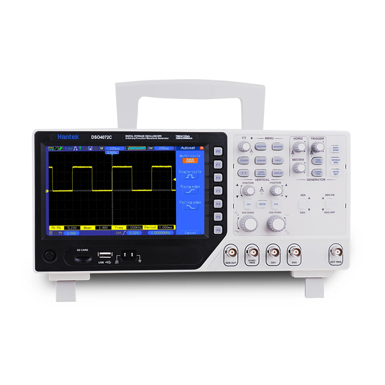
The content below simply describes and introduces the front panel and the back part of this series of digital oscilloscope so that you can get familiar with this series of digital oscilloscope well within the shortest time. Figure 1-1 Figure of Front Panel DSO4000 Series Digital Storage Oscilloscope... -
Page 10: User Interface
If this icon lights up, it means the keyboard of the oscilloscope is locked by the host computer via USB control. : If this icon lights up, it means the USB disk has been connected. DSO4000 Series Digital Storage Oscilloscope... -
Page 11: Functional Check
Plug in the oscilloscope and press the ON/OFF button. Then push the “UTILITY ->F6 ->F6 -> F6->DEFAULT” button. The default Probe option attenuation setting is 10X. 1.2.2 Connect the oscilloscope Set the switch on the probe to 10X and connect the probe to Channel 1 on the oscilloscope. First, DSO4000 Series Digital Storage Oscilloscope... -
Page 12: Observe The Waveform
Do not touch metallic portions of the probe head while it is connected to a voltage source. Connect the probe to the oscilloscope and connect the ground terminal to ground before you start any measurements. DSO4000 Series Digital Storage Oscilloscope... -
Page 13: Use Of Probe Check Wizard
3. If necessary, use a nonmetallic screwdriver to adjust the variable capacity of your probe until the shape of the waveform turns to be the same as the above figure. Repeat this step as necessary. See the figure below for the way of adjustment. DSO4000 Series Digital Storage Oscilloscope... -
Page 14: Probe Attenuation Setting
20 minutes until it has adequately warmed up. To compensate the signal path, disconnect any probes or cables from the front-panel input connectors. Then, push the UTILITY button, select the Do Self Cal option and follow the directions on the screen. DSO4000 Series Digital Storage Oscilloscope... -
Page 15: Chapter 2 Main Feature Description
Basic Operation Chapter 2 Main Feature Description This chapter provides some general information that you need to learn before using an oscilloscope. It contains: Menu and Control Keys Multi-functional Knobs and Buttons Signal Connectors Oscilloscope Setup ... - Page 16 [RUN/STOP]: continuously acquire waveform or stop acquisition [SINGLE SEQ]: Acquire a single trigger, finish acquisition and then stop. [GEN DSO]: Waveform generator output button.. [GEN ON/GEN OFF]: Power Amplifier output button. DSO4000 Series Digital Storage Oscilloscope...
-
Page 17: Multi-Functional Knobs And Buttons
‘next page’, ‘previous page’, and ‘press F6 to confirm’ appearing when you push Self Calibration option. 2.3 Signal Connectors See the figure below to find the seven signals connectors and a pair of metal electrodes at the bottom of the oscilloscope panel. GEN OUT: Waveform Signal Output. DSO4000 Series Digital Storage Oscilloscope... -
Page 18: Oscilloscope Setup
The table below gives the options, buttons and controls that change settings at default setup. Menu or System Option, Button or Knob Default Setting (Three mode options) Normal Acquire Averages Run/Stop DSO4000 Series Digital Storage Oscilloscope... - Page 19 Trigger (Video) Sync All lines Standard NTSC When Set Pulse Width 1.00ms Trigger (Pulse) Polarity Positive Mode Auto Coupling Slope Rising Mode Auto Trigger (Slope) Coupling When Type Edge Trigger (Swap) Slope Rising Mode Auto DSO4000 Series Digital Storage Oscilloscope...
-
Page 20: Horizontal System
The readout near the upper right of the screen shows the current horizontal position in second. W indicates ‘Window Time Base’. The oscilloscope also has an arrow icon at the top of the graticule to indicate the horizontal position. DSO4000 Series Digital Storage Oscilloscope... -
Page 21: Horizontal Control Knob
Left arrow Mark interested in, and searches for these marks by right and left Set/Clear arrows. Then it positions the window to this mark for further Clear All observation. DSO4000 Series Digital Storage Oscilloscope... - Page 22 The expansion time base cannot be slower than the main time base. Press the “Minor Window” button after the window is setting well. DSO4000 Series Digital Storage Oscilloscope...
-
Page 23: Display Scan Mode
At this mode, waveform display is renewed from left to right. At the mode, no waveform trigger or horizontal position control exist. The channel coupling should be set as direct current when a low-frequency signal is observed at the scan mode. DSO4000 Series Digital Storage Oscilloscope... -
Page 24: Vertical System
HF Limit Limited components. Selects the resolution of the VOLTS/DIV knob. Coarse VOLTS/DIV Coarse defines a 1-2-5 sequence. Fine changes the Fine resolution to small steps between the Coarse settings. DSO4000 Series Digital Storage Oscilloscope... -
Page 25: Math Fft
Zoom: Use the FFT Zoom button to adjust the window size. Scale: x1, x2, x5, x10. Note: All selected menus are highlighted in orange. 2.7.2 Math FFT This chapter elaborates how to use the Math FFT (Fast Fourier Transform). You can use the Math DSO4000 Series Digital Storage Oscilloscope... - Page 26 1. Push the MATH MENU button; 2. Set the Operation option to FFT; 3. Select the Math FFT Source channel. In many situations, the oscilloscope can also generate a useful FFT spectrum despite the YT DSO4000 Series Digital Storage Oscilloscope...
- Page 27 Select a type of the FFT window. For more Window Rectangular information, refer to Section 2.7.2.3. Change the horizontal magnification of the FFT FFT Zoom X1, X2, X5, X10 display. For detailed information, refer to Section 2.7.2.6. DSO4000 Series Digital Storage Oscilloscope...
- Page 28 If the number of cycles is nonintegral, the YT waveform starts and ends at different amplitudes and transitions between the start and end points will cause discontinuities in the signal that introduces high-frequency transients. DSO4000 Series Digital Storage Oscilloscope...
- Page 29 Better frequency, poorer amplitude accuracy than Flattop Waveform Periodic Flattop Better amplitude, poorer frequency accuracy than Hanning Waveform Pulse or Transient Special-purpose window applicable to discontinuous Rectangular Waveform waveforms. This is actually the same as no windows. DSO4000 Series Digital Storage Oscilloscope...
- Page 30 X1(default), X2, X5 and X10. The FFT spectrum is magnified vertically to the marker M (math waveform reference point on the left edge of the screen). Turn the VERTICAL POSITION knob clockwise to move up the spectrum. DSO4000 Series Digital Storage Oscilloscope...
-
Page 31: Trigger System
Video Trigger performs a field or line trigger through standard video signals. Pulse Width Trigger can trigger normal or abnormal pulses that meet trigger conditions. DSO4000 Series Digital Storage Oscilloscope... -
Page 32: Trigger Controls
The trigger can be defined through the Trigger Menu and front-panel controls. There are six types of trigger: Edge, Video, Pulse Width, Swap, Slope and Overtime. Refer to the following tables to find a different set of options for each type of trigger. DSO4000 Series Digital Storage Oscilloscope... - Page 33 AC Line: Uses a signal derived from the power cord as the trigger source. Select a trigger mode. Auto Mode By default, the oscilloscope uses the Auto mode. In this mode, Normal the oscilloscope is forced to trigger when it does not detect a DSO4000 Series Digital Storage Oscilloscope...
- Page 34 Note: When you choose Normal Polarity, the trigger always occurs on negative-going sync pulses. If the video signal contains positive-going sync pulses, use the Inverted Polarity option. Pulse Width Trigger You can use it to trigger on aberrant pulses. DSO4000 Series Digital Storage Oscilloscope...
- Page 35 ±5% Threshold level Tolerance Tolerance = Trigger Point =, ≠: Within a ± 5% tolerance, triggers the oscilloscope when the signal pulse width is equal to or not equal to the specified pulse width. DSO4000 Series Digital Storage Oscilloscope...
- Page 36 Below list options in submenus. Swap Trigger allows CH1 and CH2 to select different trigger modes and to display waveforms on a same screen. That is, both channels can choose the following four trigger modes. Type Edge Rising Slope Falling DSO4000 Series Digital Storage Oscilloscope...
- Page 37 Adjust the vertical window by setting two trigger levels. Vertical Select this option and press F3 to choose V1 or V2. ≠ When Select the trigger condition. < > Time 20ns to 10.0sec Press F4 to select this option. Turn the multi-functional DSO4000 Series Digital Storage Oscilloscope...
-
Page 38: Save/Recall
Press the SAVE/RECALL button to save or recall oscilloscope setups or waveforms. The first page shows the following menu. Options Settings Comments REF is used as a reference waveform. The format is custom. Source Select a waveform source to store. DSO4000 Series Digital Storage Oscilloscope... - Page 39 Close file list. File List Open Open file list. Back Return to main menu. Options Settings Comments Push the Default softkey to initialize the oscilloscope to a known Default setup. Please refer to Default Setup. DSO4000 Series Digital Storage Oscilloscope...
-
Page 40: Display System
Only horizontal coordinate and vertical coordinate in the middle of the Grid Real line level will display on the screen when grid is off. Grid 0-15 16 ranks adjustable, with a progress bar to display Intensity DSO4000 Series Digital Storage Oscilloscope... -
Page 41: Xy Format
The method realizes simple measurement by multiplying the vertical scale number of the signal with the vertical gear Volt/div. 2.11.2 Cursor measurement [CURSORS] is a function key for cursor measurement. The cursor measurement includes two modes: Manual mode and Tracking mode. DSO4000 Series Digital Storage Oscilloscope... - Page 42 B, wherein the values of the cursors will appear on the right upper corner of the screen during movement. The operation steps are as follows: 1. Press [CURSORS] to skip to the “CURSOR” menu. 2. Press “Type” to select “Voltage” or “Time”. DSO4000 Series Digital Storage Oscilloscope...
- Page 43 E→T: Position (namely the time based on the horizontal central position) of “E” in the horizontal direction. E→V: Position (namely the voltage based on the grounded point of the channel) of “E” in the vertical direction. DSO4000 Series Digital Storage Oscilloscope...
-
Page 44: Measurement
The most positive peak voltage measured over the entire waveform. Measure the time between 10% and 90% of the first rising edge of Rising the waveform. Measure the time between 90% and 10% of the first falling edge of Falling the waveform. DSO4000 Series Digital Storage Oscilloscope... - Page 45 The time between the first falling edge of source 1 and the first rising edge of source 2. The time between the first rising edge of source 1 and the first falling edge of source 2. Do not take any measurement. DSO4000 Series Digital Storage Oscilloscope...
-
Page 46: Acquisition System
Normal: For the oscilloscope model with the bandwidth of 100MHz, the maximum sample rate is 1GS/s. For time base with insufficient sample rate, you may use the Sine Interpolation Algorithm to interpolate points between sampled points to produce a complete waveform record (4K by default). DSO4000 Series Digital Storage Oscilloscope... - Page 47 Second Acquisition Third Acquisition Fourth Acquisition As shown above, acquire input signals (cycle repeatable) for more than once at a slow sample rate, arrange the sample points by the time they appear, then recover waveforms. DSO4000 Series Digital Storage Oscilloscope...
-
Page 48: Utility System
This series of oscilloscope can upgrade the software by the USB flash disc, which needs about 5 minutes. The firmware is upgraded by the following steps: 1. Plug the USB flash disc in which a firmware program is saved in USB Host interface DSO4000 Series Digital Storage Oscilloscope... -
Page 49: Self Calibration
“Pass/fail” is used for judging whether the input signal is in a built rule range and outputting the past or failed waveform so as to detect the change condition of the signal. Page 1 of the pass/fail function menu: DSO4000 Series Digital Storage Oscilloscope... - Page 50 Back Back to page of the rule setup menu. Pass/Fail output The pass/fail function can be used for outputting a negative pulse train through a Pass/Fail BNC interface on a rear panel of the oscilloscope. DSO4000 Series Digital Storage Oscilloscope...
-
Page 51: Recorder
6. Select the “Time interval” option, and use the [V0] knob to regulate the time interval of frame to frame in waveform recording. 7. Select the “End frame” option, and use the [V0] knob to regulate the maximal frame number in the waveform recording. DSO4000 Series Digital Storage Oscilloscope... -
Page 52: Filter
Down: Set the lower limit of the cutoff frequency. All the signals from down to up frequency can be passed. And other signals will be limited. Band Stop Up: Set the upper limit of the cutoff frequency. DSO4000 Series Digital Storage Oscilloscope... -
Page 53: Wave
Press “Utility->F6->F6” to page 3 and select “Option->DDS” of utility menu to enable to waveform generator function. 2.13.13 DVM Press “Utility->F6->F6” to page 3 and select “Option->DVM” of utility menu to calculate the Root Mean Square voltage over the entire waveform(CRMS). DSO4000 Series Digital Storage Oscilloscope... -
Page 54: Help System
Turn the HELP SCROLL knob to highlight a help topic. Press the Show Topic option button to display the topic. NOTE: Press the Exit option button or any menu button to remove the Help text from the screen and return to displaying waveforms. DSO4000 Series Digital Storage Oscilloscope... -
Page 55: Fast Action Buttons
Set to 50% Trigger Mode Auto Trigger Source Adjusted; Autoset can not be used for the EXT TRIG signal Trigger Slope Adjusted Trigger Type Edge Trigger Video Sync Adjusted Trigger Video Standard Adjusted Vertical Bandwidth Full DSO4000 Series Digital Storage Oscilloscope... - Page 56 Set the horizontal scale to display about one cycle of the waveform. Single-cycle Square The oscilloscope displays Min, Mean and Positive Width automatic measurements. Rising Edge Display the rising edge. Falling Edge Display the falling edge. Undo Setup Let the oscilloscope recall the previous setup. DSO4000 Series Digital Storage Oscilloscope...
-
Page 57: Waveform Generator
“WaveEditorSetup.exe” in WaveEditor folder in CD disk and install Arbitrary Waveform Editor software according to installation wizard. After the software installed successfully, you can see WaveEditor icon on desktop. Double-click the icon to enter arbitrary waveform generator window. DSO4000 Series Digital Storage Oscilloscope... - Page 58 Duty cycle is defined as the time that the signal spends above zero volts divided by the total cycle time. Thus, a symmetrical square or triangular wave has a duty cycle of 50%. Reducing the duty DSO4000 Series Digital Storage Oscilloscope...
-
Page 59: Output Arbitrary Waveform
3. Press F1 or F2 softkey to select Arb1~Arb4. 4. Press F6 softkey twice to enter recall menu, and select desired recalled ARB and CSV format file in USB disk. 5. The waveform will output from GEN OUT BNC port. DSO4000 Series Digital Storage Oscilloscope... -
Page 60: Power Amplifier(Optional)
However, to prevent damage to power amplifier’s performance, long time short circuit output should be avoided. Please also avoid to frequently using the maximum value of the frequency, amplitude and load. Power Amp Out Power Out: Turn on or turn off power amplifier out. DSO4000 Series Digital Storage Oscilloscope... -
Page 61: Chapter 3 Application Examples
Chapter 3 Application Examples This chapter unfolds a further description on main features of the oscilloscope by giving eleven simplified application examples for reference to help solve your own test problems. Taking simple measurements Using AUTOSET Using the Measure menu to take auto measurements Taking cursor measurements Measuring ring frequency and ring amplitude Measuring pulse width... -
Page 62: Example 1: Taking Simple Measurements
V0 to select a measure item and go back to the measure interface. The corresponding box under the measure item shows the measurements. Repeat Step 2 and Step 3. Then select other measure items. Totally 8 measure items can be displayed. Note: All readouts change with the measured signals. DSO4000 Series Digital Storage Oscilloscope... -
Page 63: Example 2: Taking Cursor Measurements
Put Cursor S on the highest peak of the ring. 10. Put Cursor E on the lowest point of the ring. The amplitude of the ring will be displayed at Delta. See figures below for better understanding. DSO4000 Series Digital Storage Oscilloscope... - Page 64 Place Cursor S on the rising edge of the pulse and Cursor E on the falling edge. Thus at Delta displays the measured time and at Cursor S and Cursor E displays the time relative to the trigger. See the figure below for better understanding. DSO4000 Series Digital Storage Oscilloscope...
- Page 65 Select Cursor E and turn V0 to place it at the 90% level of the waveform. 10. The Delta readout in the Cursor Menu is the rise time of the pulse. See the figure below for better understanding. DSO4000 Series Digital Storage Oscilloscope...
- Page 66 Press the ACQUIRE button to see the Acquire menu. Push the Type option button and select Real Time. Push the Peak Detect option button. If necessary, push the DISPLAY button and set the Contrast option to view the noise more clearly. DSO4000 Series Digital Storage Oscilloscope...
- Page 67 Push the Averages option button and adjust the number of running averages to watch the change in the waveform display. Note: Averaging reduces random noise and let you view the signal details more easily. See the figure below for better understanding DSO4000 Series Digital Storage Oscilloscope...
-
Page 68: Example 4: Capturing Single-Shot Signal
Connect the oscilloscope with circuitry and view the input and output of the circuit in XY mode. Follow the steps below. First, prepare two oscilloscope probes and set the switches to 10X on both probes. DSO4000 Series Digital Storage Oscilloscope... - Page 69 (π/2~π) or (π-3π/2). See the figure below for better understanding. Signal Horizontal Centering DSO4000 Series Digital Storage Oscilloscope...
-
Page 70: Example 6: Triggering On Pulse Width
‘≠’ or ‘<’ to trigger on the pulse. As shown in the above figure, you can get a stable waveform display if inputting a square wave at the frequency of 1KHz, with pulse width set to 500μs. DSO4000 Series Digital Storage Oscilloscope... -
Page 71: Example 7: Triggering On Video Signal
Push the Source option button to select CH1; push the Polarity option button to select Normal; push the Standard option button to select NTSC; push the Sync option button to select Line Number. Turn the Trigger Level knob to adjust the trigger level and stabilize video signals. DSO4000 Series Digital Storage Oscilloscope... - Page 72 Click the ‘Next Page’ button and select Vertical. Turn the V0 knob to adjust V1 and V2 to proper locations. Select the When option button and set it to ‘=’. Select ‘Time’ and turn V0 to adjust the time until you get a stable display of waveforms. See the figure below. DSO4000 Series Digital Storage Oscilloscope...
-
Page 73: Example 9: Using Overtime Trigger To Measure Long Pulse Signal
Turn V0 to adjust the line number (NTSC: 0-525 lines). Turn the horizontal SEC/DIV and the vertical VOLTS/DIV knobs to display on the screen a complete video signal triggering on a video line. See the figure below. DSO4000 Series Digital Storage Oscilloscope... -
Page 74: Example 10: Using Math Functions To Analyze Waveforms
Note: You should compensate both probes before performing the math operation; otherwise, differences in probe compensation will appear as errors in the differential signal. As illustrated in the above figure, input a 1KHz sine wave from CH1 and a 1KHz square wave from DSO4000 Series Digital Storage Oscilloscope... -
Page 75: Example 11: Measuring Data Propagation Delay
Select Cursor S and turn V0 to place it on the active edge of the enable signal. Select Cursor E and turn V0 to place it on the data output transition (See the figure below). 10. Read the data propagation delay in the Delta readout. DSO4000 Series Digital Storage Oscilloscope... - Page 76 DATA DATA DSO4000 Series Digital Storage Oscilloscope...
-
Page 77: Chapter 4 Troubleshooting
SET TO 50% button to reset the trigger level back to the center of the signal; 3) Check the trigger mode to confirm it is a right choice for the input signal. The default trigger mode is edge trigger. However, it is not suitable for all kinds of input signals. DSO4000 Series Digital Storage Oscilloscope... -
Page 78: Chapter 5 Specifications
Specifications Chapter 5 Specifications 5.1 Technical Specifications All specifications herein mentioned apply to the DSO4000 series oscilloscopes. Before checking an oscilloscope from your seller to see if it complies with these specifications, make sure it meets the following conditions: ... - Page 79 100MHz; 350mV (Edge Trigger Type) 100MHz from 100MHz to 200MHz 1V from DC to 1V from DC to 100MHz; EXT/5 100MHz 1.75V from 100MHz to 200MHz Attenuates signals below 10Hz HF Reject Attenuates signals above 80kHz DSO4000 Series Digital Storage Oscilloscope...
- Page 80 Positive slope or Negative slope Equal: The oscilloscope triggers when the waveform slope is equal to the set slope. Slope Trigger Point Not Equal: The oscilloscope triggers when the waveform slope is not equal to the set slope. DSO4000 Series Digital Storage Oscilloscope...
- Page 81 Average N can be set to 4, 8, 16, 32, 64 or 128 Inputs Inputs Input Coupling DC, AC or GND Input Impedance, 1MΩ±2% in parallel with 20pF± 3pF DC coupled Probe Attenuation 1X, 10X DSO4000 Series Digital Storage Oscilloscope...
- Page 82 Operating: 32℉ to 122℉ (0℃ to 50℃) Temperature Nonoperating: -40℉ to 159.8℉ (-40℃ to +71℃) Cooling Method Convection +104℉ or below (+40℃ or below): ≤90% relative humidity Humidity 106℉ to 122℉ (+41℃ to 50℃): ≤60% relative humidity DSO4000 Series Digital Storage Oscilloscope...
- Page 83 Wave Amplitude ± 3.5V Max. 50 Ω Output Impedance Output Current 50mA, Ipeak=50mA System BW Harmonic Distortion -50dBc(1KHz), -40dBc(10KHz) Power Amplifier(Optional) 7W(8 Ω), 1W(50 Ω) Maximum power output Maximum output voltage 22Vpp Frequency bandwidth 1Hz~200KHz DSO4000 Series Digital Storage Oscilloscope...
-
Page 84: Accessories
A software installation CD. It contains the user manual of DSO4000, giving particular descriptions on the DSO4000 series oscilloscopes. *. To this digital storage oscilloscope, the PC software is not important, no more advanced functions are developed. For example, 1. For the function of "export into Excel format", there is aleady "Save into CSV"... -
Page 85: Chapter 6 General Care And Cleaning
2) Use a soft cloth dampened with water to clean the oscilloscope. For more efficient cleaning, you may use an aqueous solution of 75% isopropyl alcohol. Note: To avoid damage to the surface of the oscilloscope or probes, do not use any corrosive or chemical cleaning agents. DSO4000 Series Digital Storage Oscilloscope... -
Page 86: Appendix A Harmful And Poisonous Substances Or Elements
‘0’ indicates that the content of this poisonous and harmful substance in all homogeneous materials of this component is refrained under the limit stated in the SJ/T 11363-2006 standard. This component list contains components approved in the file ‘Management Measures’. DSO4000 Series Digital Storage Oscilloscope... -
Page 87: Gnu General Public License
Also, for each author's protection and ours, we want to make certain that everyone understands that there is no warranty for this free software. If the software is modified by someone else and DSO4000 Series Digital Storage Oscilloscope... - Page 88 Section 1 above, provided that you also meet all of these conditions: a) You must cause the modified files to carry prominent notices stating that you changed the files and the date of any change. DSO4000 Series Digital Storage Oscilloscope...
- Page 89 Sections 1 and 2 above on a medium customarily used for software interchange; or, c) Accompany it with the information you received as to the offer to distribute corresponding source code. (This alternative is allowed only for noncommercial distribution and only if you DSO4000 Series Digital Storage Oscilloscope...
- Page 90 Program by all those who receive copies directly or indirectly through you, then the only way you could satisfy both it and this License would be to refrain entirely from distribution of the Program. DSO4000 Series Digital Storage Oscilloscope...
- Page 91 NO WARRANTY 11. BECAUSE THE PROGRAM IS LICENSED FREE OF CHARGE, THERE IS NO WARRANTY FOR THE PROGRAM, TO THE EXTENT PERMITTED BY APPLICABLE LAW. EXCEPT WHEN OTHERWISE STATED IN WRITING THE COPYRIGHT HOLDERS AND/OR DSO4000 Series Digital Storage Oscilloscope...
- Page 92 PURPOSE. See the GNU General Public License for more details. You should have received a copy of the GNU General Public License along with this program; if not, write to the Free Software Foundation, Inc., 51 Franklin Street, Fifth Floor, Boston, MA 02110-1301 USA. DSO4000 Series Digital Storage Oscilloscope...
- Page 93 If your program is a subroutine library, you may consider it more useful to permit linking proprietary applications with the library. If this is what you want to do, use the GNU Lesser General Public License instead of this License. DSO4000 Series Digital Storage Oscilloscope...
Need help?
Do you have a question about the DSO4000 Series and is the answer not in the manual?
Questions and answers