Table of Contents
Advertisement
Available languages
Available languages
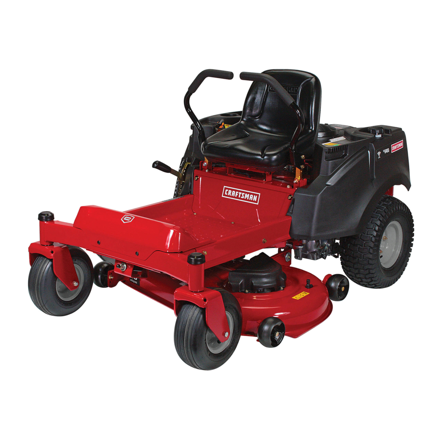
Operator's Manual
ZTS 7500
Zero-Turn Rear Engine Riders with Electric Start
Model No.
107.27768
(19HP Briggs
& Stratton
with 42" Mower)
CAUTION:
Before using this product,
read
the manual and follow all its Safety Rules
and Operating
Instructions,
For answers to your questions
about this
product, call:
1-800-659-5917
Sears Craftsman
Help Line
5 am - 5 pm, Mon- Sat
Nota: Una traducci6n
en espaSol
de este Manual
del Operador
puede encontrarse
en la pAgina
33.
Sears, Roebuck and Co., Hoffman Estates, IL 60179
U.S.A.
Visit our Craftsman website: www.sears.com/craftsman
TP 199-4276-06-CZ-C
1732838
Revision 08
Advertisement
Table of Contents

Related Manuals for Craftsman 19HP BRIGGS & STRATTON WITH 42" MOWER 107.27768


Summary of Contents for Craftsman 19HP BRIGGS & STRATTON WITH 42" MOWER 107.27768
- Page 1 Before using this product, the manual and follow all its Safety Rules and Operating Instructions, Sears, Roebuck and Co., Hoffman Estates, IL 60179 Visit our Craftsman website: www.sears.com/craftsman & Stratton with 42" Mower) For answers to your questions read product, call:...
-
Page 2: This Warranty Does Not Cover
For your convenience, IN HOME warranty service will still be available after the first 30 days of purchase, but a trip charge will apply. This charge will be waived if the Craftsman product is dropped off at an authorized Sears loca- tion. -
Page 3: General Operation
Read thesesafety rulesandfollow themclosely. F ailure toobeytheserulescouldresult i n lossofcontrol of unit,severe personal injury or deathtoyou,or bystanders, or damage toproperty or equipment. This mowing deck is capable of amputating hands and feet and throwin og_bjb'ects. The triangle _, in text signifies important cautions or warnings which must be followed. GENERAL OPERATION 1. -
Page 4: Slope Operation
SLOPE OPERATION Slopes are a major factor related to loss-of-control and tip- over accidents, which can result in severe injury or death. Operation on all slopes requires extra caution. If you cannot back up the slope or if you feel uneasy on it, do not operate on it. -
Page 5: Service And Maintenance
SERVICE AND MAINTENANCE Safe Handling of Gasoline 1. Extinguish all cigarettes, cigars, pipes, and other sources of ignition. 2. Use only approved gasoline containers. 3. Never remove the gas cap or add fuel with the engine running. Allow the engine to cool before refueling. 4. -
Page 6: Safety & Operation Decals
SAFETY & OPERATION This unit has been designed and manufactured to pro- vide you with the safety and reliability you would expect from an industry leader in outdoor power equipment manufacturing. Although reading this manual and the safety instructions it contains will provide you with the necessary basic knowledge to operate this equipment safely and effec- tively, we have placed several safety labels on the unit to remind you of this important information while you are... - Page 7 The identification tag is located on the underside of the seat. Tilt the seat forward to access the ID tag. For answers to your questions about this product, call: 1-800-659-5917 Sears Craftsman Help Line, 5 am - 5 pm, Monday-Saturday. Model Description Name/Number...
- Page 8 - Two Bin Bagger - Headlight • Front Bumper Setup instructions - English Setup in 6 E_y Step: Troubleshooting Keys Setup instructions - Operator's Spanish Book - English/Spanish Ope_to¢_ Manual Setup i_, _ _asv Step_: ZTS 7_00 ,,=_ _, Troubleshooting Manual &...
- Page 9 Read The Operator's Manual • Read the operator's manual. You should always read and follow the instructions in the operator's manual. Proper care, performance tips, and safety information is located in this important document. Always Check the Oil Level • Check the engine oil level. The engine in your tractor has been shipped, from the factory, already filled with oil for use during the engine break-in period.
-
Page 10: Control Functions
Left GroundSpeed& ParkingBrake Lever Fuel Tank I__ _ _1_1 Ground SpeedLevers - Ground SpeedLevers - DRIVEPesitens PARK Pesitens CONTROL FUNCTIONS The information below briefly describes the function of individual controls. Starting, stopping, driving, and mowing require the combined use of several controls applied in specific sequences. To learn what combination and sequence of controls to use for various tasks please read the entire section. -
Page 11: Ignition Switch
Mower Height of Cut Adjustment To adjust cutting height, rotate the turn crank clockwise to raise the mower deck and counterclockwise the mower deck. ignition Switch The ignition switch starts and stops the engine; it has three positions: Stops the engine and shuts off the electrical system. -
Page 12: Before Starting
CHECKS BEFORE STARTING • Check that the crankcase oil is filled to full mark on dipstick. • Fill the fuel tank with fresh fuel. FUEL RECOMMENDATIONS For daily operation: Use only unleaded gasoline with a pump sticker octane rating of 87 or higher. Gasohol (up to 10% ethyl alcohol, 90% unleaded gasoline by volume) is approved as a fuel. - Page 13 EMERGENCY STOPPING In the event of an emergency the engine can be stopped by simply turning the ignition switch to STOR Use this method only in emergency situations. shut down follow the procedure given in STOPPING THE RIDER AND ENGINE. STOPPING THE RIDER &...
-
Page 14: Forward Travel
DRiViNG PRACTICE- BASIC DRIVING WARNING: Never operate on slopes greater than 17.6% (10°). See SLOPE OPERATION in the safety section. Zero turn riders operate differently from other bur- wheeled vehicles. The drive wheels are also your steer- ing wheels. If you cannot drive the unit on a hill, you will not be able to steer the unit on it. - Page 15 Practice Turning Around a Corner While traveling forward allow one handle to gradually return back toward neutral. Practice several times before mowing. NOTE." To prevent damaging your lawn by pivoting direct- ly on the tire tread, it is best to keep both wheels going at least slightly forward.
-
Page 16: Mower Deck Removal Installation
MOWER DECK REMOVAL INSTALLATION NOTE: Perform mower removal and installation on a hard, level surface such as a concrete floor. WARNING Engage parking brake, disengage PTO, stop engine and remove key before attempting install or remove the mower. Removing Mower Deck 1. -
Page 17: Engine Maintenance
MAINTENANCE SCHEDULE The following schedules should be followed for normal care of your rider and mower. RIDER MAINTENANCE, All Models Clean Debris from Rider and Engine Compartment * Clean Debris from Engine Cooling Areas & Air Filter * Check Tire Pressure Lubricate Rider &... -
Page 18: Rider Maintenance
Rider Maintenance CLEAN DEBRIS FROM RIDER AND ENGINE COMPARTMENT Service IntervaJ: Before each use. CAUTION: if debris is not removed from the engine compartment and other hot surfaces, it creates a fire hazard. Before starting the unit at the beginning of the mowing session, remove any grass clippings, dirt, leaves, or other debris from the unit. - Page 19 LUBRiCATiON Service Interval: 25 hours. Lubricate the unit at the locations shown in Figures 15 through 17 as well as the following lubrication points. Grease: • front wheel bushings • mower pivots ,, front wheel grease fittings • mower arbors Use grease fittings when present.
-
Page 20: Mower Blades
CLEAN DECK & CHECK / REPLACE MOWER BLADES Service Intervah 25 hours or as required. WARNING For your personal safety, do not handle the sharp mower blades with bare hands. Careless or improper handling of blades may result in serious injury. -
Page 21: Cleaning The Battery And Cables
CLEANING THE BATTERY AND CABLES WARNING Be careful when handling the battery. Avoid spilling electrolyte. Keep flames and sparks away from the battery. When removing or installing battery cables, disconnect the negative cable FIRST and reconnect it LAST. if not done in this order, the positive terminal can be shorted to the frame by a tool. -
Page 22: Check / Adjust
CHECK / ADJUST PTO CLUTCH • ILWARNING To avoid serious injury, perform adjustments with engine stopped, key removed and tractor on level ground. Service interval: 200 Hours. The PTO clutch is engaged and disengaged by the PTO switch. The clutch powers and brakes the mower blades. Check the PTO clutch adjustment every 200 hours of operation. -
Page 23: Check Engine Oil Level
CHECK ENGINE OIL LEVEL Service Interval: Before each use, and every 8 hours. 1. Turn the engine off, and set the parking brake to PARK. 2. Clean the area around the dip stick (C, Figure 25). 3. Remove the dip stick (C) and clean it with a paper towel. - Page 24 AiR FILTER & PRE-CLEANER Service interval: Pre-Cleaner: Every 25 hours or as required. Air Filter: Every 50 hours or as required. Replacement interval: Pre-Cleaner: As required. Air Filter: Every 200 hours or once per season. Air Filter Removal & Installation 1.
-
Page 25: Air Filter Service
Pre=Cleaner Service NOTE: Replace a worn or damaged pre-cleaner. 1. Figure 28. Wash the pre-cleaner in liquid detergent and water. 2. Squeeze the pre-cleaner dry and saturate with engine oil. Remove all excess oil by squeezing the pre-cleaner in an absorbent cloth. Air Filter Service NOTE: Replace a worn or damaged air filter. -
Page 26: Ground Speed Control Lever Adjustment
GROUND SPEED CONTROL ADJUSTMENT The control levers have three adjustments: To Adjust Control Lever Height: Pull the levers in across the operator's lap to their DRIVE positions. Loosen the mount bolts (D, Figure 30) and raise or lower the levers to the desired position. Tighten the mounting bolts.(D). - Page 27 CUTTING HEIGHT ADJUSTMENT Turn the cutting height adjustment crank (A, Figure 31) clockwise to raise the mower deck and counterclockwise to lower it. If the crank is difficult to turn, thoroughly clean and lubricate it. PTO CLUTCH ADJUSTMENT See CHECK / ADJUST PTO CLUTCH in the Maintenance Section.
-
Page 28: Mower Deck Leveling Adjustments
MOWER DECK LEVELING ADJUSTMENTS WARNING Before checking mower, shut off PTO and engine. Allow all moving parts to stop. Remove ignition key, then disconnect the spark plug wire and fasten it away from the spark plug. Side to Side Leveling If the cut is uneven, the mower may need leveling. -
Page 29: Front To Back Leveling
Figure 36. Orient Blades Front-to=Back Front To Back Leveling If the cut is uneven, the mower may need leveling. Unequal or improper tire pressure may also cause an uneven cut. See CHECK TiRE PRESSURE. 1. Turn the blades front-to-back as shown in Figure 36. Measure the distance from the ground to front tip of center blade, and from ground to rear tips of left hand and right hand blades (Figures 36). - Page 30 STO RAG E Before you store your unit for the off-season, read the Maintenance and Storage instructions in the Safety Rules section, then perform the following steps: • Disengage the PTO, set the ground speed control levers to PARK, & remove the key. Check all fluid levels.
-
Page 31: Troubleshooting
While normal care and regular maintenance will extend the life of your equipment, prolonged or constant use may eventually require that service be performed to allow it to continue operat- ing properly. The troubleshooting guide below lists the most common problems, their causes and remedies. If you prefer, all of these procedures can be performed for you by a Sears Parts &... - Page 32 Engine Transmission release levers in PUSH runs, but rider will not 9ositions. drive. Drive belt slips. Belt is broken. Parking brake is not fully released. Rider drive belt Pulleys or belt greasy or oily. slips. Belt stretched or worn. Parking brake Parking brake is incorrectly adjusted.
- Page 33 Para obtener respuestas tiene un mot sobre este producto, difer- fono-(sin Antes que 1-800-659-5917 Servicio de ayuda Sears Craftsman 5 am - 5 pm, Lunes a Sabado de 42") a qualquier pregunta Ilame al num6ro de tel& cobro) siguiente:...
- Page 34 GARANTJA LIMITADA DEL EQUIPO MONTABLE DE CRAFTSMAN Pot dos (2) aSos a partir de la fecha de compra, si este equipo montable de Craftsman es mantenido, lubficado y afinado conforme alas instrucciones en el manual del propietafio, Sears repararb, o reemplazarA sin costo alguno cualquier parte que se encuentre defectuosa en material o mane de obra conforme a los lineamientos de la cobertura enumerada a contin- uacidn.
- Page 35 Leaestasreglas deseguridad y sigalas concuidado. Noobedecer e stasreglas puedeocasionar la p6rdida delcontrol s obrelaunidad, l esiones severas a la persona o lamuerte deusted, o espectadores, o daffos a la propiedad o alequipo.Estacubiertade la podadora es capazdeamputarmanosy piesy dearrojar _etos. Eltriangulo,_ eneltextodenota precauciones o advertencias importantes quedeben obedecerse. OPERACION GENERAL 1.
-
Page 36: Sistema De Encendido
OPERACION EN CUESTAS Las cuestas son un factor importante relacionado con los acci- dentes por perdida de control y volcaduras, y pueden propiciar lesiones severas o la muerte. Cualquier operaci6n en cuestas exige precauciones extremas. Si usted no puede dar marcha atrAs en una cuesta o se siente inquieto en ella, no opere en ella. - Page 37 SERViCiO Y MANTENilVllENTO Manejo Seguro de la Gasolina 1. Apague cigarros, puros, pipas y otras fuentes de ignici6n. 2. Use s61o los contenedores aprobados para gasolina. 3. Nunca quite el tap6n de la gasolina ni cargue combustible con el motor encendido. Permita que el motor se enfrie antes de poner combustible.
- Page 38 CALCOMANiAS DE SEGURIDADY OPERACION Esta unidad fue diseSaday fabricada para ofrecerle la seguridad y confiabilidad que usted esperaria de un Ifder en la indus- tria de la fabricacidn de equipos motorizados para el exterior. Aunque leer este manual y las medidas de seguridad que contiene le proporcionara, el conocimiento ba.sico necesario para operar este equipo sin percances y eficazmente, hemos colocado varias etiquetas de seguridad en la unidad para...
- Page 39 Para obtener respuestas a sus preguntas sobre el pro- ducto, Ilame al: 1-800-659-5917 Servicio TelefSnico de Asistencia de Sears Craftsman, 5 am - 5 pro, Lunes - S_.bado. servicio o infor=...
- Page 40 - Recolector de Hierba con Bolsa - Faro delantero Instrucciones Disposici6n - Ingles Setup in 6 E_y _tep: Troubleshooting Llaves Gemela Instrucciones Disposici6n - EspaSol Setup ,,=_ _, 2._ _2:_:_ s._ _2_)_u_ Troubleshooting IVianual del Operador y Libro de Partes - Ingl_s/EspaSol Ope_to¢_ Manual ZTS 7_OO...
- Page 41 Leer el Manual del Operador Usted siempre debe leer y seguir las instrucciones en el manual del Operador. En este importante docu- mento encuentra informaci6n sobre el debido cuidado, consejos de rendimiento y seguri- dad. Siempre Verificar Nivel del Aceite El motor en su tractor fue embarca- do, de fabrica, Ileno con aceite 10W- 30 de peso para usar durante el...
- Page 42 Palanca de Velocidad Izquierda & Freno de Mano Tap6n del Tanque de Gasolina Palancas de Velocidad - Palancas de Velocidad - Posici6n de DRIVE Posici6n de PARK FUNClONES DE CONTROL La informaci6n abajo describe brevemente la funci6n de los controles individuales. Arrancar, detenerse, conducir y podar el cesped requiere del uso combJnado de varios controles aplicados en secuencias especificas.
- Page 43 Ajuste de AJtura de Corte Para ajustar la altura de corte, gire la manivela a la derecha para subir la cubierta de la podadora y a la izquierda para bajar la cubierta de la podadora. Interruptor de Encendido El interruptor de encendido arranca y detiene el motor; tiene tres posiciones: OFF (apagado) Detiene el motor y corta el sistema el6ctrico.
-
Page 44: Antes De Arrancar
VERIFICACIONES ANTES DE ARRANCAR ,, Verifique que el aceite del c_rter este en la marca de Ileno de la varilla de nivel de aceite. ,, Llene el tanque de gasolina con combustible fresco. RECOMENDACIONES DE COMBUSTIBLE Para operaci6n diaria: Use s01ogasolina sin plomo donde la calcomanfa de la bomba indiqueun octanaje de 87 o mayor. -
Page 45: Paro De Emergencia
PARO DE EMERGENCIA En el caso de una emergencia, el motor puede detenerse simple- mente girando el interruptor de encendido a STOR Use este metodo solo en situaciones de emergencia. motor normalmente, siga el procedimiento EL TRACTOR Y EL MOTOR. COMO PARAR EL MONTABLE MOTOR 1. - Page 46 PR. ,CTICA DE IVIANEJO - MANEJO BASlCO ADVERTENClA: Nunca opere en cuestas mayoras a 17.6% (10°). Vea OPERACION EN CUESTAS en la secci6n de seguridad. Los tractores de giro cero operan de modo difer- ente a otros vehiculos de cuatro ruedas. Las ruedas de trac- ci6n tambien son sus ruedas de direcci6n.
-
Page 47: Manejo A Vanzado
Prbctica de dar Vuelta en una Esquina Mientras viaja hacia adelante permita que una palanca regrese gradualmente en direcci6n del neutral. Practique varias veces antes de podar el cesped. NOTA: Para evitar girar directamente sobre la banda de rodamiento, es mejor mantener /as dos ruedas en mar- cha hacia adelante aunque sea ligeramente. - Page 48 REMOCION E INSTALACION CUBIERTA DE LA PODADORA NOTA:Ejecute la remocidn e instalacidn de la podadora sobre una supefficie dura y nivelada como un piso de concreto. ADVERTENCIA Accione el freno de mano, desacople detenga el motor y quite la llave antes de intentar instalar o quitar la podadora.
-
Page 49: Mantenimiento
PROGRAMA DE MANTENiMIENTO El siguiente programa debe seguirse para el cuidado normal de su tractor y podadora. MANTENIMIENTO DEL MONTABLE, de todos los modeJos Limpie el residuo del montable y del compartimiento del motor * Limpie el residuo de las areas de refdgeraci6n del motor y del filtro de aire * Verifique la presi6n de las Ilantas Lubrique el montable y la segadora... - Page 50 Elementos de Mantenirniento del Tractor LIMPIAR DESPOJOS DEL TRACTOR Y DEL COMPARTIMIENTO DEL MOTOR Intervalo de Servicio: Antes de cada uso. PRECAUCION: Si no se quitan los despojos del com- partimiento del motor y otras superficies calientes, se crea un peligro de incendio. unidad al inicio de la sesi6n de podado de c_sped, elim- ine cualquier hierba cortada, mugre, hojas u otros despojos de la unidad.
- Page 51 LUBRICACI6N IntervMo de Servicio: 25 horas. Lubrique la unidad en los lugares mostrados en las Figuras 15 a 17 asi como en los siguientes puntos de lubricaci6n. Grasa: • engrasadores de la rueda delantera • bujes de la rueda delantera •...
- Page 52 LiMPIAFt CUBIERTA Y VERIFICAFI/ REEMPLAZAFI ASPAS DE PODADORA Intervalo de Servicio: 25 horas o segOn se requiera. ADVERTENCIA Para su seguridad personal, no maneje las aspas afiladas de la podadora con las manos descubiertas. El manejo imprudente de las aspas puede resultar en lesiones ADVERTENCIA Para su seguridad personal, los tornillos cabeza de montaje de las cuchillas deben...
- Page 53 LIMPIAR BATERiAY CABLES ADVERTENCIA Tenga cuidado al manejar la bateda. Evite derramar el electrolito. Mantenga chispas lejos de la bateria. Cuando quite o instale los cables de la bateria, desconecte PRIMERO el cable negativo y con_ctelo al ULTIMO. Si no se hace en este orden, la terminal causar un cortocircuito al bastidor...
- Page 54 VERIFICAR/AJUSTAR EMBRAGUE DEL PTO ADVERTENCIA Para evitar lesiones graves, s61o haga los ajustes con el motor detenido, la Ilave quitada y el tractor en terreno niveiado. Intervalo de Servicio: 200 horas. El embrague del PTO se embraga y desembraga con el interruptor PTO.
- Page 55 VERIFIQUE EL NIVEL DE ACEITE DEL MOTOR Intetvalo de servicio: Antes de cada uso, y cada 8 horas. 1. Apague el motor, y coloque el freno de parada en la posicion de PARK (parado). 2. Limpie el Area alrededor de la varilla para medici6n del nivel (C, Figura 25).
- Page 56 SERVlCIO DEL FILTRO DE AIREY PURIFICADOR - IVIODELOS BRIGGS STRATTON Intervalo de servicio: Prepurificador: cada 25 horas o conforme sea necesario. Filtro de aire: cada 50 horas o conforme sea necesario. Intetvalo de reemplazo: Prepurificador: conforme sea necesario. Filtro de aire: cada 200 horas o una vez por estaci6n.
- Page 57 Servicio del prepurificador NOTA: Remplace el prepurificador do o desgastado. 1. Figura 28. Lave el prepurificador con detergente Ifquido y agua. 2. Exprima el prepurificador para que quede seco y saturelo con aceite de motor. Remueva todo el aceite en exceso exprimiendo el prepurificador en una toalla absorbente.
- Page 58 AJUSTE DE PALANCA DE CONTROL DE VELOCIDAD Las palancas de control tienen tres ajustes: Para Ajustar la AItura de las Palancas de Control: Jale las palancas hacia adentro, encima del regazo del operador a la posici6n de DRWE. Afloje los pernos de montaje (D, Figura 30) y suba o baje las palancas a la posici6n deseada.
- Page 59 AJUSTE DE LA ALTURA DE CORTE Gire la manivela del ajuste de la altura de corte (A, Figura 31) a la derecha para subir la cubierta de la podadora y a la izquierda para bajarla. Si se le dificulta girar la manivela, Ifmpiela bien y lubrfquela.
- Page 60 AJUSTE DE NIVEL DE LA CUBIERTA DE LA PODADORA ADVERTENCIA Antes de verificar la podadora, apague el PTO y el motor. Permita que se detengan todas las partes en movimiento. Quite la llave del encendido, luego desconecte el cable de la bujia y suj_telo lejos de la bujia.
- Page 61 Figura 36. Orientar las Aspas de Adelante hacia Atrbs Nivelado de Adelante hacia Atr_s 1. Gire las aspas de adelante hacia atr4s como se muestra en la Figura 36. MJda la distancia delantera del aspa central, y del suelo a la punta trasera de las aspas Jzquierda y derecha (Figura 37).
- Page 62 ALMACENAMIENTO Antes de almacenar su unidad en la temporada instrucciones de Mantenimiento y Almacenamiento ci6n de Reglas de Seguridad, luego realice los siguientes pasos: ,, Desacople el PTO, ponga el freno de mano y quite la Ilave. Verifique el nivel de todos los fiuidos. Verifique todos los elementos de mantenimiento.
- Page 63 ADVERTENCIA Para evitar lesiones graves, realice el mantenimiento podadora s61o con el motor apagado y el freno de mano en PARK. Siempre quite la llave del encendido, desconecte y suj_telo lejos de la buj{a antes de empezar para evitar que el motor arranque accidentalmente. Diagn6stico del Tractor PROBLEMA...
- Page 64 El motoropera Laspalancas d edesembrague de la _eroel tractor transmisi6n e nposici6n de EMPUJAR. no avanza. Labandadetracci6n sebarre. LabandaestArota. Freno demanonoestAdesaccionadoContacte Partes y Reparaciones deSears. Bandadetrac- Poleas o labanda congrasao aceite. Limpie segQn se requiera. ci6n se barre. La banda esta estirada o desgastada. El freno de mano El freno de mano esta mal ajustado.
-
Page 65: Repair Parts
RepairParts PTS - 1... -
Page 66: Frame, Body & Seat Group
Frame, Body & Seat Group (987349) NOTE: Unless noted otherwise, use the standard hardware torque specification chart, _.-*Kohler 17 61-- Torque Capscrew to 72-77 ft. Ibs. or 97.6-104.4 PTS-2 ZTS 7500 107.27768 Engine Only,... - Page 67 Frame, Body & Seat Group REF NO PART NO. QTY. DESCRIPTION 1726018SM SEAT ASSEMBLY, with Arm Rests (Includes Ref. No. 68) 1687021SM ARM REST KIT, (L.H. & R.H.) 1727332ASM SUPPORT, Seat 1960694SM NUT, Hex Flange ESNA, 1/4-20 1960738SM CAPSCREW, 1728044SM DECK, Seat 1960715SM SCREW, Truss Head Torx Drive, 1/4-20 x 3/4...
- Page 68 Frame, Body & Seat Group (987349) NOTE: Unless noted otherwise, use the standard hardware torque specification chart, _.-*Kohler 17 61-- Torque Capscrew to 72-77 ft. Ibs. or 97.6-104.4 PTS-4 ZTS 7500 107.27768 Engine Only,...
- Page 69 Frame, Body & Seat Group REF NO PART NO. QTY. DESCRIPTION 1960368SM NUT, Speed Lug Type, 1/4-20 1930641SM NUT, Hex Flange Whiz Lock, 1/4-20 1930644SM NUT, Hex Flange Two-Way Lock, 1/2-13 1709235SM SPACER 1716064ASM HOOK & WASHER ASSEMBLY 1960518SM NUT, Push, 1/4 1726504SM CAP, Hub 1931317SM...
- Page 70 Engine Group - 19HP Briggs & Stratton NOTE: Unless noted otherwise, use the standard hardware torque specification chart. Engine Manuafacturer for service parts. Torque to 18 ft. tbsp. or 24.4 (987321) F" 31 / \\ C"- NOTE: Apply anti-seize compound to crankshaft before installing pulley.
- Page 71 Engine Group - 19HP Briggs REF NO PART NO. QTY. DESCRIPTION ENGINE, 19HP B&S Intex Twin, Model # 31 P877 Type # 0121-E1 1732257ASM SHIELD, Heat Inner 1936228SM CAPSCREW, 1917356SM LOCKWASHER, 1732259SM PIPE, Exhaust B&S Intek 1731214SM GASKET, Exhaust B&S 1960295SM CAPSCREW, 1927557SM...
- Page 72 Carrier & Transmission Group (987362) NOTE: Unless noted otherwise, use the standard hardware torque specification chart. Black Apply Grease Control Rods 9 to be positioned toward centerline Apply Greese Ref. Nos. 5 and with bends of unit, Apply Grease Yellow PTS - 8 ZTS 7500 107.27768...
- Page 73 Carrier & Transmission Group REF NO PART NO. QTY. DESCRIPTION 1960687SM NUT, Hex Flange ESNA, 3/8-16 1960684SM NUT, Hex Keps, 5/16-18 1703900SM SPACER 1960223SM CARRIAGE BOLT, 5/16-18 x 1, G5 1727555SM ROD, Control, L.H. 1919381SM WASHER, 5/16 1728060SM HYDRO SEAL KIT 1727831SM BOLT, Shoulder, 7/16-14, G5 1727556SM...
- Page 74 Carrier & Transmission Group (987362) NOTE: Unless noted otherwise, use the standard hardware torque specification chart. Black Apply Grease Control Rods 9 to be positioned toward centerline Apply Greese Ref. Nos. 5 and with bends of unit, Apply Grease Yellow PTS - 10 ZTS 7500 107.27768...
- Page 75 Carrier & Transmission Group (987362) REFNO PARTNO. QTY. DESCRIPTION 1728075SM PARKING BRAKE ARM ASSEMBLY, 1687283SM HUB REPLACEMENT 1733870SM HUB, EZT Transmissions 5020601SM NUT, EZT Transmissions Footnotes Transmission L.H. or R.H. PTS-11 ZTS 7500-107.27768...
- Page 76 Controls Group (986806) NOTE: Unless noted otherwise, use the standard hardware torque specification chart. 6-12 Ibs inwardforce measured 1,,_ 1" above bottomof foam grips (bothsides). j÷ Frame Brakearmto be full in gear teeth. PTS - 12 ZTS 7500 107.27768 Handlebarsout (locked) brakespringto 3"...
- Page 77 Controls Group (986806) REFNO PART NO. QTY. DESCRIPTION 1725927SM SHAFT, Cross 1960027SM WASHER, 1/2 1703805SM RING, Klipring Extension 1921977SM CAPSCREW, 1920161SM NUT, Hex Jam, 5/16-18 1960717SM NUT, Speed, 5/16-18 Lug Type 1960686SM NUT, Hex Flange, 5/16-18 ESNA 1728009ASM BRACKET, L.H. Mounting Handle Pivot 1727919SM CLIP, Brake 1727663ASM...
- Page 78 Electrical Group (986808_986894) NOTE: Unless noted otherwise, use the standard hardware torque specification chart. Headlight S witch (Optional) _---_. Seat Switch Clip harness to seat p an, Tie Harness to throttle cable Electric Clutch PTS - 14 ZTS 7500 - 107.27768 To Engine Block TOStarterBolt...
- Page 79 Electrical Group (986808_986894) REF NO PART NO. QTY. DESCRIPTION 1732006SM SWITCH, Push Button 1686734SM SWITCH ASSEMBLY, 1960547SM LOCKWASHER, 1717549SM NUT, Hex Flange, 5/8-32, Ignition Switch 1717550SM COVER, Ignition Switch 1717163SM KEYS (Set of Two Keys) 1731185SM METER, Hour Digital with Oil & Lube Alarms 1722611SM PLUG, Hole 1722887SM...
- Page 80 Wheels & Tires Group (W987352 987357_987358_986884_986857_987350}_TS 7500- 107.27768 NOTE: Unless noted otherwise, use the standard hardware torque specification chart. fi;' Torque 44 - 55 ft. Ibs. or 59.4 - 74.8 Nm PTS-16...
- Page 81 Wheels & Tires Group (W987352 REF NO PART NO. QTY. DESCRIPTION 2860183SM WASHER 2830647SM NUT, Hex Lock PAL, 3/4-20 1722675SM CAP, Hub 1726383SM WHEEL & TIRE ASSEMBLY, 2172353SM VALVE STEM & CAP 5020601SM NUT, Hex Lug, 1/2-20 1726382SM WHEEL & TIRE ASSEMBLY, 1713167SM BUSHING, Wheel 2812808SM...
- Page 82 Decals Group (D987352 987357_987358_986884_986857_987350) ZTS 7500 - 107.27768 NOTE: Unless noted otherwise, use the standard hardware torque specification chart. 14 j PTS - 18...
- Page 83 Seat Deck Stripe, R.H. Engine Do Not Remove Foam Seal Seat Deck Stripe, L.H. ZTS 7500 (1942) ZTS 7500 (2044) ZTS 7500 (2250) CRAFTSMAN Panel Upper, Operation Panel Lower, Warning/Danger & Icon Indicator Tracking Transmission Release Valve Height of Cut...
- Page 84 42" Mower Deck - Clutch & Support Group (987323) ZTS 7500 107.27768 NOTE: Unless noted otherwise, use the standard hardware torque specification chart. Clutch NOVABLE IDLER PULLEY MOVABLE IDLER PULLEY ARBOR DRIVE PULLEY PTS - 20...
- Page 85 42" Mower Deck - Clutch & Support DESCRIPTION REF NO PART NO. QTY. 1713578SM ROD, 7-5/8 Long 2176012SM RETAINER, Pin Spring 1728124ASM HITCH, Mower 1726012SM ROD, ZTR 1960519SM NUT, Push 1/2 Stud Capped 1919439SM NUT, Hex Lock ESNA Light, 3/8-16 NC3B 1732225ZSM HITCH, Mower Front 42"...
- Page 86 42" Mower Deck - Height Adjustment NOTE: Unless noted otherwise, use the standard hardware torque specification chart. Group (987324) PTS - 22 ZTS 7500 107.27768...
- Page 87 42" Mower Deck - Height Adjustment REF NO PART NO. QTY. DESCRIPTION 2108765SM BOLT, Wheel, 3/8-16 x 2-25/32 3/4 Thread 1960170SM WASHER, 1/2 1714760SM GAUGE WHEEL 1731403ZSM BRACKET, Gauge Wheel LH Back 1960687SM NUT, Hex Flange ESNA, 3/8-16 1732258ZSM BRACKET, Gauge Wheel LH Front 1732244ZSM BRACKET, Rear LH 42"...
- Page 88 42" Mower Deck - Housing, NOTE: Unless noted otherwise, use the standard hardware torque specification chart. TORQUE 80-90 FT/LBS 108.8 - 122.4 Arbors & Blades Group (987322) PTS - 24 ZTS 7500 107.27768 TORQUE TO 35-75 FT/LBS or 88.4-102 LUBE FITTING...
- Page 89 42" Mower Deck - Housing, REF NO PART NO. QTY. DESCRIPTION 1960576SM NUT, Hex Lock ESNA Light. 5/8-18 1734064SM PULLEY, 7072440SM SPACER, Pulley 7012491SM RETAINING 2108202SM BEARING, Ball 1731372ZSM TUBE & PLATE ASSEMBLY, Spindle 1704314SM LUBE FITTING, 1/4 Drive w/Check Ball 7072537SM SHAFT, Spindle 1730100CSM...
- Page 90 Briggs & Stratton Engine Parts 358 ENGINE GASKET SET 524@ 1058 OWNER'S MANUAL 1036 EMISSIONS LABEL 1330 REPAIR MANUAL 943 O 1022 _ 617 0 1266A 691_ 842 0 750 & 1O27 PTS - 26 ZTS 7500 Model No. 107.27768 684111 _ 584_ 1264_...
-
Page 91: Briggs & Stratton Engine
Briggs & Stratton Engine Parts ZTS 7500-Model No. 107.27768 1095 VALVE GASKET SET 1022 868@ 238 ® 1022 842JT 654@ 1022 1023 5240 232_ 334 _' PTS - 27... - Page 92 Briggs & Stratton Engine Parts 1267 801 _'_ 803_ 310 1 697 _' 57%46_ _/, _ 503_ 602 <_ 1266A< > 1266 121 CARBURETOR OVERHAUL KIT 617 0 95 _ 987 _ lO4_ [2Z_ 105 0 305A 306 _ 1040 1270 1266A 276 @...
- Page 93 Briggs & Stratton Engine Parts REF. PART NOTES DESCRIPTION 697174 Cylinder Assembly 399265 Kit-Bushing/Seal Side) 391086s Seal-Oil (Magneto Side) 697188 Sump-Engine 698147 Head-Cylinder 699168 Gasket-Cylinder Gasket-Breather 697109 Tube-Breather 697113 Gasket-Crankcase 697110 690360 Screw (Cylinder Head) 690946 Plug-Oil Drain Crankshaft 697127 690947 Seal-Oil (PTO Side) 692125...
- Page 94 Briggs & Stratton Engine Parts PART NOTES DESCRiPTiON 790832 Screw (Oil Pump Cover) 697607 Link-Counterweight 897134 Counterweight 697392 Pin-Counterweight 693713 Gear-Pinion 898329 Harness-Wiring 789A 790544 Harness-Wiring 693167 Nut (Brush Retainer) 691283 Cap-Drive 691286 Cap-End Housing-Starter order complete starter motor reference 309) 691095 Stud (Rocker Arm) 691031...
-
Page 95: Hardware Identification& Torquespecifications
Hardware identification& TorqueSpecifications Common Hardware Types Hex Head Capscrew (((((((((((((((((((() {(((((((((((((((((( O Carriage Belt ¢ (((((((((((((((((((() ((((((((((((((({(((( O Standard Hardware Sizing When a washer or nut is identified as 112", this Nominal size, meaning the inside diameteris second number is present it represent the threads When... - Page 96 PTS - 32...
- Page 97 U.S.A. call 1-800-4-MY-HOME@ Acuerdo Felicidades por su compra inteligente. Su nuevo produc- to de Craftsman@ fue dise_ado y fabricado para a_os de operaci6n confiable. Pero come todos los productos, es posible que cada cierto tiempo requiera de reparaciones.
- Page 98 For repair-in your home-of lawn and garden equipment, no matter who made it, no matter who sold it! For the replacement owner's manuals that you need to do-it-yourself. For Sears professional and items like garage door openers and water heaters. 1-800-4-MY-HOME Call anytime, www.sears.corR...
Need help?
Do you have a question about the 19HP BRIGGS & STRATTON WITH 42" MOWER 107.27768 and is the answer not in the manual?
Questions and answers
How do I remove the air filter?
To remove the air filter on a Craftsman 19HP with 42" mower model 107.27768:
1. Lift up on the bottom of the latch and flip it away from the cover.
2. Remove the air filter cover.
3. Remove the air filter and the pre-cleaner.
This answer is automatically generated