Advertisement
Available languages
Available languages
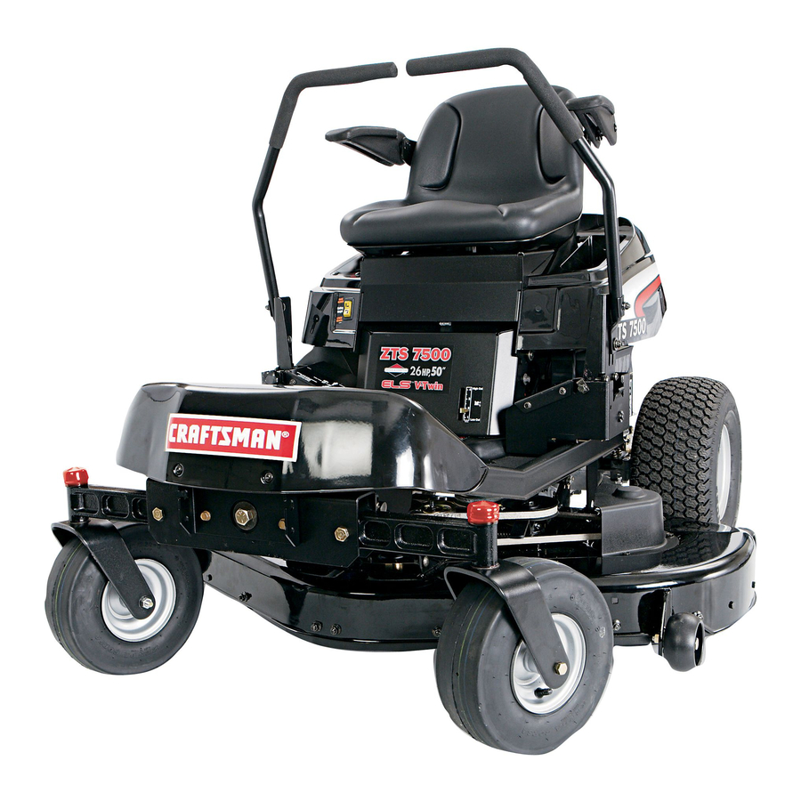
Operator's Manual
ZTS 7500
Zero-Turn Rear Engine Rider with
Electric Start
Model No.
107.28790
(26 HP Briggs & Stratton Engine with 50" Mower)
CAUTION:
Before using this product,
read
the manual and follow all its Safety Rules
and Operating
Instructions.
For answers to your questions
about this
product, call:
1-800-659-5917
Sears Craftsman
Help Line
5 am - 5 pm, Mon- Sat
Nota: Una traducci6n
en espaSol
de este Manual
del Operador
puede encontrarse
en la pagina
33.
Sears, Roebuck and Co., Hoffman Estates, IL 60179
U.S.A.
Visit our Craftsman website: www.sears.com/craftsman
TP 899-4839-00-CZ-C
7102150
Revision 00
Advertisement

Related Manuals for Craftsman 28790 - 26 HP 50 in. Zero Turn Tractor Mower


Summary of Contents for Craftsman 28790 - 26 HP 50 in. Zero Turn Tractor Mower
- Page 1 5 am - 5 pm, Mon- Sat Nota: Una traducci6n en espaSol de este Manual del Operador puede encontrarse en la pagina Sears, Roebuck and Co., Hoffman Estates, IL 60179 U.S.A. Visit our Craftsman website: www.sears.com/craftsman TP 899-4839-00-CZ-C 7102150 Revision 00...
-
Page 2: Table Of Contents
For your convenience, IN HOME warranty service will still be available after the first 30 days of purchase, but a trip charge will apply. This charge will be waived if the Craftsman product is dropped off at an authorized Sears location. - Page 3 Read thesesafety rulesandfollow themclosely. F ailure toobeytheserulescouldresult i n lossofcontrol of unit,severe personal injury or deathtoyou,or bystanders, or damage toproperty or equipment. This mowing deck is capable of amputating hands and feet and throwing objects. The triangle _ in text signifies important cautions or warnings which must be followed. GENERAL OPERATION 19.
- Page 4 SLOPE OPERATION -,AWARNING Slopes are a major factor related to loss-of-control and tip- Never operate on slopes greater than 17.6 percent over accidents, which can result in severe injury or death. (10 °) which is a rise of 3-1/2 feet (106 cm) vertically in Operation on all slopes requires extra caution.
- Page 5 SUGGESTED GUIDE FOR SiGHTiNG SLOPES FOR SAFE OPERATION OF RIDER WiTH ATTACHMENT ONLY RiDE UP AND DOWN HILL, NOT ACROSS HiLL 10 DEGREES MAX. WARNING: To avoid serious injury, operate your unit up and down the face of slopes, never across the face. Do not operate on slopes greater than 10 degrees.
- Page 6 SERVICE AND MAINTENANCE 13. If the fuel tank must be drained, it should be drained outdoors. Safe Handling of Gasoline 14. Replace faulty silencers/mufflers. 1. Extinguish all cigarettes, cigars, pipes, and other 15. Maintain or replace safety and instruction labels as sources of ignition.
- Page 7 SAFETY & OPERATION DECALS This unit has been designed and manufactured to provide you with the safety and reliability you would expect from an industry leader in outdoor power equipment manufacturing. Although reading this manual and the safety instructions it contains will provide you with the necessary basic knowledge to operate this equipment safely and effectively, we have placed several safety labels on the unit to remind you of this important information while you...
-
Page 8: Identification Numbers
Tilt the seat forward to access the ID tag. Model Description Name/Number For answers to your questions about this product, call: 1-800-659-5917 Stock Number Jnit Serial Number Sears Craftsman Help Line, 5 am - 5 pm, Monday-Saturday. Date Purchased ..Engine Make Engine Model Engine Type/Spec... - Page 9 Remove the Packaging Materials Fill-Up with FRESH Gasoline Remove the cardboard from the crate. Lift the seat deck to access the Remove any steel branding securing the unit to the crate. Locate the manual Remove the fuel tank cap and fill packet.
- Page 10 Right Left Ground Speed & GroundSpeed Control Lever ParkingBrake Lever Mower cutting Height Switch Choke Ground Speed L evers - Greged S peed Levers - DRIVE Positons START/PARK Positons (Closed) Choke (Open) FuelTank Engine Speed (Fast) CONTROL FUNCTIONS The information below briefly describes the function of individual controls.
-
Page 11: Operation
Mower Blade Switch Mower Cutting Height Switch To increase the mower cutting height (raise the mower The yellow mower blade switch turns the mower blades deck), press the top of the yellow mower cutting height on and off. To turn the mower blades ON, pull the switch switch. - Page 12 CHECKS BEFORE STARTING • Check that the crankcase oil is filled to full mark on dipstick. • Fill the fuel tank with fresh fuel. FUEL RECOMMENDATIONS For daily operation: Use only unleaded gasoline with a pump sticker octane rating of 87 or higher. Gasohol (up to 10% ethyl alcohol, 90% unleaded gasoline by volume) is approved as a fuel.
- Page 13 EMERGENCY STOPPING PUSHING THE RIDER BY HAND In the event of an emergency the engine can be stopped NOTE: Do not disengage the transmissions while parked by simply turning the ignition switch to STOE Use this on a slope. method only in emergency situations. For normal engine 1.
- Page 14 DRIVING PRACTICE- Smooth Travel The lever controls of the BASIC DRIVING zero turn rider are WARNING: Never operate on slopes greater than 17.6% highly responsive. (10°). See SLOPE OPERATION in the safety section. The BEST method of Zero turn riders operate differently from other four- handling the ground wheeled vehicles.
- Page 15 Practice Turning Around a Corner Practice Turning In Place While traveling forward allow one handle to gradually To "zero turn" means to turn in place. To turn in place, return back toward neutral. Practice several times before gradually move one ground speed control lever forward from neutral and one lever back from neutral mowing.
- Page 16 MOWER DECK REMOVAL & INSTALLATION NOTE: Perform mower removal and installation on a hard, level surface such as a concrete floor. WARNING After lowering the mower cutting height, engage parking brake, turn off the mower blades, turn the ignition switch to STOP, and remove key before attempting to install or remove the mower.
-
Page 17: Maintenance
MAINTENANCE SCHEDULE The following schedules should be followed for normal care of your rider and mower. RIDER MAINTENANCE, All Models Before Spring Yearly Each Use & Fall Hours Hours Hours Hours Clean Debris from Rider and Engine Compartment * Clean Debris from Engine Cooling Areas & Air Filter * Check Tire Pressure Lubricate Rider &... - Page 18 Rider Maintenance Items WARNING Move the ground speed levers to START/PARK positions, turn the mower blades OFF, turn the ignition switch OFF, and wait for all moving parts to stop before accessing the engine compartment or performing any maintenance procedures. ACCESSING THE ENGINE COMPARTMENT...
- Page 19 LUBRICATION Service Interval: 25 hours. Lubricate the unit at the locations shown in Figures 15 through 19 as well as the following lubrication points. Grease: • front wheel bushings • mower pivots • front wheel grease fittings • mower arbors Use grease fittings when present.
- Page 20 CLEAN DECK & CHECK / REPLACE MOWER BLADES Service Interval: 25 hours or as required. WARNING For your personal safety, do not handle the sharp mower blades with bare hands, Careless or improper handling of blades may result in serious injury, LOOSEN WARNING...
- Page 21 CLEANING THE BATTERY AND CABLES CHECK RIDER SAFETY Service Interval: t O0 Hours SYSTEM WARNING Service Interval: Every 100 hours, every spring/fall, Corrosion hazard. and after storage of 30 days or longer. Batteries contain acid. Always keep the This unit is equipped with safety interlock switches. battery upright and do not spill the These safety systems are present for your safety.
- Page 22 CHECK / ADJUST PTO CLUTCH WARNING To avoid serious injury, perform adjustments only with engine stopped, key removed and tractor on level ground. Service Interval: 200 Hours. The Power Take Off (PTO) clutch drives the mower blades. The PTO clutch is engaged and disengaged by the mower blade switch.
- Page 23 Engine Maintenance Items Use oil classified API Service Class SF, SG, SH, SJ or betterwith SAEViscosity: CHECK ENGINE OIL LEVEL Service Interval: Before each use, and every 8 hours. 1. Turn the engine off, and set the parking brake to PARK.
- Page 24 Figure 28. Air Filter Cover Figure 29. Air Filter Removal A. Air Filter Cover Screws A. Filter Cartridge Figure 30. Air Filter Installation A. Filter Cartridge...
- Page 25 REPLACE SPARK PLUG Service Interval: Every 100 hours. Spark Plug Gap: .030" (.76mm) .030" 1. Stop the engine and allow it to cool. 2. Clean the area around the spark plug. 3. Remove the spark plug. 4. Check the spark plug gap. It should be .030" (see Figure 31 ).
- Page 26 GROUND SPEED CONTROL LEVER ADJUSTMENT The control levers have three adjustments: To Adjust Control Lever Height: Pull the levers in across the operator's lap to their DRIVE positions. Loosen the mount bolts (D, Figure 32) and raise or lower the levers to the desired position. Tighten the mounting bolts.(D).
- Page 27 BRAKE ADJUSTMENT 1. Stop the unit, turn the ignition OFE set the ground speed levers to PARK positions, and wait for all moving parts to stop. ,3" (7.62cm) 2. Locate the brake rod (A, Figure 34) and adjustment nut (B). 4.
- Page 28 MOWER DECK LEVELING ADJUSTMENTS WARNING Before adjusting the mower, turn the mower blades OFF, turn the ignition switch OFF, remove the key, and allow all moving parts to stop. Disconnect the spark plug wire and fasten it away from the spark plug. Figure 35.
- Page 29 Figure 38. Orient Blades Front-to-Back Front To Back Leveling If the cut is uneven, the mower may need leveling. Unequal or improper tire pressure may also cause an uneven cut. See CHECK TIRE PRESSURE. Figure 43. Front-to-Back Leveling 1. Turn the blades front-to-back as shown in Figure 38. A.
-
Page 30: Storage
STORAG E WARNING Storage Before Never store the unit (with fuel) in an enclosed, Before you store your unit for the off-season, read the poorly ventilated structure. Fuel vapors can Maintenance and Storage instructions in the Safety travel to an ignition source (such as a furnace, Rules section, then perform the following steps: water heater, etc.) and cause an explosion. -
Page 31: Troubleshooting
While normal care and regular maintenance will extend the life _WARNING of your equipment, prolonged or constant use may eventually require that service be performed to allow it to continue To avoid serious injury, perform maintenance on operating properly. The troubleshooting guide below lists the the rider or mower only when the engine is most common problems, their causes and remedies. - Page 32 Transmission release levers in PUSH Engine runs, but Move levers to DRIVE positions, rider will not 3ositions. drive. Drive belt slips. Clean or replace belt as necessary. Belt is broken. Replace drive belt. Contact Sears Parts & Repair. Parking brake is not fully released. Contact Sears Parts &...
- Page 33 Antes que 1-800-659-5917 arranque el motor, lea y comprenda Manual del DueSo. Servicio de ayuda Sears Craftsman 5 am - 5 pm, Lunes a Sabado...
- Page 34 DE CRAFTSMAN Por dos (2) aSos a partir de la fecha de compra, si este equipo montable de Craftsman es mantenido, lubricado y afinado conforme alas instrucciones en el manual del propietario, Sears reparara o reemplazara sin costo alguno cualquier parte que se encuentre defectuosa en material o mano de obra conforme a los lineamientos de la cobertura enumerada a contin- uaci6n.
- Page 35 Leaestasreglas deseguridad y sfgalas concuidado. Noobedecer e stasreglas puedeocasionar la perdida delcontrol s obrelaunidad, l esiones severas a la persona o lamuerte deusted, o espectadores, o daSos a la propiedad o alequipo.Estacubiertade la podadora es capazdeamputarmanosy piesy dearrojar _'etos. Eltriangulo _ eneltextodenota precauciones o advertencias importantes quedeben obedecerse. OPERACION GENERAL uar su habilidad de operar el equipo con la suficiente...
- Page 36 OPERACION EN CUESTAS - iL ADVERTENCIA Las cuestas son un factor importante relacionado con los acci- dentes por perdida de control y volcaduras, y pueden propiciar Nunca opere en cuestas mayores a 17.6 por ciento lesiones severas o la muerte. Cualquier operaci6n en cuestas (10 °) Io cual es una inclinaci6n de 3 1/2 pies (106 cm) exige precauciones extremas.
- Page 37 SERVICIO Y MANTENIMIENTO 11. No quite el filtro de la gasolina cuando el motor esta caliente ya que la gasolina que se derrame se puede incen- Manejo Seguro de la Gasolina diar. No extienda las abrazaderas de la tuberfa del com- 1.
- Page 38 CALCOMANIAS DE SEGURIDADY OPERACION Esta unidad fue diseSaday fabricada para ofrecerle la seguridad y confiabilidad que usted esperaria de un lider en la indus- tria de la fabricaci6n de equipos motorizados para el exterior, Aunque leer este manual y las medidas de seguridad que contiene le proporcionara el conocimiento basico necesario para operar este equipo sin percances y eficazmente, hemos colocado varias etiquetas de seguridad en la unidad para...
- Page 39 GU|A SUGERIDA PARA EL AVISTAIVllENTO DE PENDIENTES PARA UNA OPERACION SEGURA DEL IVIONTABLE CON ACCESORIO CONDUZCA SOLO HACIA ARRIBAY HACIA ABAJO POR LA PENDIENTE NUNCA DE UN LADO A OTRO 10 GRADOS MAXIMO ADVERTENCIA: Para evitar lesiones graves, opere la unidad hacia arriba y hacia abjo per la pendiente, nunca de un lado a otro.
- Page 40 Para obtener respuestas a sus preguntas sobre el pro- ducto, Ilame ah 1-800-659-5917 Fecha de Compra Servicio Telef6nico de Asistencia de Sears Craftsman, 5 am - 5 pm, Lunes - Sabado. Marca del Motor Modelo del Motor...
- Page 41 Llenar con Gasolina FRESCA Retirar los Materiales de Empaque Quite el cart6n del caj6n de embalaje. Levante el asiento para ganar Quite el encintado de acero que sujeta acceso al tap6n de la gasolina y la unidad al caj6n de embalaje. Ubique al tanque.
- Page 42 Palanca de Control Palanca de de Velocidad de _" Velocidad de Avance Izquierda Avance Derecha & Freno de Mano Ajuste de Altura de Corte Palancas de Velocidad - Palancas de Velocidad - Posici6n de DRIVE Posici6n de PARK hogador (Cerrado) Ahogador (Abierto) Tap6n del...
- Page 43 Interruptor de Cuchillas de la Sesgadora Ajuste Sesgadora de Altura de Corte de la Para aumentar la altura de corte de la sesgadora (elevar El interruptor de cuchillas de la sesgadora amarillo activa la cubierta de la sesgadora), oprima la parte superior del y desactiva las cuchillas de la sesgadora.
- Page 44 VERIFICACIONES ANTES DE ARRANCAR • Verifique que el aceite del carter este en la marca de Ileno de la varilla de nivel de aceite. • Llene el tanque de gasolina con combustible fresco. RECOMENDACIONES DE COMBUSTIBLE Para operaci6n diaria: Use s61ogasolina sin plomo donde la calcomanfa de la bomba indique un octanaje de 87 o mayor, El gasohol (hasta 10% de alcohol etflico, 90% de gasolina sin plomo por volumen) esta aprobado como combustible, El...
- Page 45 PARO DE EMERGENCIA EMPUJAR EL MONTABLE MANUALMENTE En caso de emergencia, el motor puede detenerse simple- 1. Desactive las cuchillas de la sesgadora, empuje las mente girando el interruptor de encendido a STOP (paro). Use palancas de control de velocidad de avance a la posi- este metodo s61o en situaciones de emergencia.
- Page 46 PRACTICA DE MANEJO Traslado sin prob- lemas MANEJO BASICO Los controles de palanca ADVERTENCIA: Nunca opere en cuestas mayoras a 17.6% del tractor de giro cero son (10°). Vea OPERACION EN CUESTAS en la seccion de altamente sensibles. seguridad. Los tractores de giro cero operan de modo difer- El MEJOR metodo de ente a otros vehfculos de cuatro ruedas.
- Page 47 Prbctica de dar Vuelta en una Esquina Lugar Prbctica de Vuelta en el Mientras viaja hacia adelante permita que una palanca Hacer un "giro cero" significa girar en el mismo lugar. regrese gradualmente en direcci6n del neutral. Practique Para dar la vuelta en el mismo lugar, gradualmente varias veces antes de podar el cesped.
- Page 48 REMOCION E INSTALACION DE LA CUBIERTA DE LA SESGADORA NOTA: Ejecute la remocion e instalacidn de la sesgadora sobre una superficie dura y nivelada como un piso de concreto. ADVERTENCIA Despues de bajar la altura de corte de la sesgadora, accione el freno de mano, desactive las cuchillas de la sesgadora, gire el interruptor de encendido a STOP y quite la Ilave antes de intentar instalar o retirar la...
- Page 49 PROGRAMA DE MANTENIMIENTO El siguiente programa debe seguirse para el cuidado normal de su tractor y podadora. MANTENIMIENTO DEL MONTABLE, de todos los Antes de Primavera y Anual modelos cada uso Verano Horas Horas Horas Horas mente Limpie el residuo del montable y del compartimiento •...
- Page 50 Elementos de Mantenimiento del Tractor GANAR ACCESO AL COMPAR- TIMIENTO DEL MOTOR Levante la parte posterior del asiento para ganar acceso al compartimiento del motor. LIMPIAR DESPOJOS DEL TRACTOR Y DEL COMPARTIMIENTO DEL MOTOR Intervalo de Servicio: Antes de cada uso. PRECAUCl0N: Si no se quitan los despojos del com-...
- Page 51 LUBRICACION Intervalo de Servicio: 25 horas. Lubrique la unidad en los lugares mostrados en las Figuras 15 a 19 asf como en los siguientes puntos de lubricaci6n. Grasa: • engrasadores de la rueda delantera • bujes de la rueda delantera •...
- Page 52 LIMPIAR CUBIERTA Y VERIFICAR/ REEMPLAZAR ASPAS DE PODADORA Intervalo de Servicio: 25 horas o segQn se requiera. ADVERTENCIA Para su seguridad personal, no maneje las aspas afiladas de la podadora con las manos descubiertas. El manejo imprudente o indebido Afloje de las aspas puede resultar en lesiones graves, ADVERTENCIA Figura 20.
- Page 53 LIMPIAR BATER|AY CABLES ADVERTENCIA REVISAR SISTEMA SEGURIDAD DEL MONTABLE Peligro de corrosibn. Las baterias contienen acido. Conserve la bateria siempre de pie y no derrame el electrolito. Intervalo de servicio: Cada 100 horas, cada primavera y Evite el contacto con la piel y los ojos. otoSo y despues de estar guardado per mas de 30 dfas.
- Page 54 VERIFICAR/AJUSTAR EMBRAGUE DEL PTO ADVERTENCIA Para evitar lesiones graves, s61o haga los ajustes con el motor detenido, la Ilave quitada y el tractor en terreno nivelado. Intervalo de Servicio: 200 horas. El embrague de la Potencia de arranque (Power Take Off o PTO) acciona las cuchillas de la sesgadora.
- Page 55 Elementos de Mantenimiento Use aceite de Servicio clasificado para API de Clase SG, SH, SJ o mejor con viscosidad SAE. del Motor VERIFIQUE EL NIVEL DE ACEITE DEL MOTOR Intervalo de servicio: Antes de cada uso, y cada 8 horas. 1.
- Page 56 Figura 28. Cubierta del Filtro de Aire Figura 29. Remocibn del Filtro de Aire A. Tornillos de la Cubierta del Filtro de Aire A. Cartucho del filtro Figura 30. Instalacibn del filtro de aire A. Cartucho del filtro...
- Page 57 REEMPLACE LA BUJ|A DE ENCENDIDO Intervalo de servicio: 100 horas Separacibn de la bujia de encendido: .030" (.76mm) ,030" 1. Pare el motor y espere a que se enfrie. 2. Limpie el Area alrededor de la bujia de encendido. 3. Remueva la bujia de encendido. 4.
- Page 58 AJUSTE DE PALANCA DE CONTROL DE VELOCIDAD Las palancas de control tienen tres ajustes: Para Ajustar la Altura de las Palancas de Control: Jale las palancas hacia adentro, encima del regazo del operador a la posici6n de DRIVE. Afloje los pernos de montaje (D, Figura 32) y suba o baje las palancas a la posici6n deseada.
- Page 59 AJUSTE DEL FRENO Pare la unidad, Gire la ignici6n en la posici6n OFF (apaga- do), coloque las palancas de velocidad en suelo en la posi- cion PARK (parado), y espere a que todas las piezas que ,3" (7.62cm) se encuentren en movimiento dejen de moverse. Localice la varilla de freno (A, Figura 34) y la turca de ajuste (B).
- Page 60 AJUSTE DE NIVEL DE LA CUBIERTA DE LA PODADORA -,/k ADVERTENCIA Antes de realizar ajustes a la sesgadora, desactive las cuchillas de la misma, gire el interruptor de encendido para apagar el motor, quite la Ilave y espere a que se detengan todas las piezas mbviles. Desconecte el cable de bujias y sujetelo lejos de la misma.
- Page 61 Figura 38. Orientar las Aspas de Adelante hacia Atras Nivelado de Adelante hacia Atrbs 1. Gire las aspas de adelante hacia atras como se muestra en la Figura 38. Mida la distancia del suelo a la punta delantera del aspa central, y del suelo a la punta trasera de las aspas izquierda y derecha (Figuras 35 y 38).
- Page 62 ALMACENAMIENTO ADVERTENCIA Antes de almacenar su unidad en la temporada baja, lea las instrucciones de Mantenimiento y Almacenamiento Nunca almacene la unidad (con combustible) en en la secci6n de Reglas de Seguridad, luego realice los una estructura cerrada con poca ventilacibn. siguientes pasos: vapores del combustible pueden viajar a una •...
- Page 63 ADVERTENCIA Si Io prefiere, todos estos procedimientos pueden ser ejecutados para usted por un Para evitar lesiones graves, realice el mantenimiento del tractor o la Centro de Partes y Reparaciones de podadora solo con el motor apagado y el freno de mane en PARK. Sears.
- Page 64 El motoropera Laspalancas d edesembrague de la Mueva laspalancas a laposici6n de DRIVE. _eroel tractor transmisi6n e nposici6n de EMPUJAR. no avanza. Labandadetracci6n sebarre. Limpie o reemplace l abandasegOn seanecesario. Labandaestarota. Reemplace banda. Contacte Partes y Reparaciones deSears. Freno demanonoestadesaccionadoContacte Partes y Reparaciones deSears. Bandadetrac- Poleas o labanda congrasao aceite.
- Page 65 RepairParts PTS - 1...
- Page 66 Frame, Body & Seat Group ZTS 7500 107.28790 NOTE: Unless noted otherwise, use the standard hardware torque specification chart, To be assembled between Ref. Nos. 64 114 33 & 57 _'_- Torque Ref. No, 11 to 150 Ft. Lbs, or 204 Nm.
- Page 67 Frame, Body & Seat Group ZTS 7500-107.28790 DESCRIPTION REF NO PART NO. QTY. 1733448ASM CASTER ASSEMBLY 1960160SM WASHER, 3/4 ID x 1.60D x .05 THK 1611710SM RING, Klipring, 3/4 1734135SM CAP, Hub 1730186SM BUSHING, Axle Pivot 1733426SM AXLE, Casting (Includes Ref. Nos. 1, 2, 3, 4 & 5) 1733571SM BOLT, Shoulder, G5 1960687SM...
- Page 68 Frame, Body & Seat Group ZTS 7500 107.28790 NOTE: Unless noted otherwise, use the standard hardware torque specification chart, To be assembled between Ref. Nos. 64 114 33 & 57 _'_- Torque Ref. No, 11 to 150 Ft. Lbs, or 204 Nm.
- Page 69 Frame, Body & Seat Group ZTS 7500 107.28790 REFNO PART NO. QTY. DESCRIPTION 7090189SM LOCKWASHER, External Tooth, 3/8 7024340SM SPACER 1734257SM TANK, Fuel 1714020SM CAP, Fuel Tank 1921977SM CAPSCREW, Hex Head, 5/16-18 x 1-1/4, G5 1933988SM NUT, Push Pal, 5/16 DIA Thread, 5/80D 1727810ASM BRACE, Tank 1726390SM...
- Page 70 Engine Group - 26HP Briggs & Stratton ZTS 7500 107.28790 NOTE: Unless noted otherwise, use the standard hardware torque specification chart. Apply edge of foam paratleI _j32 to engine air cleaner cover edge with end against Ref. No. 14 & to miss rotating screen left side between rear shroud &fueI tank Torque Ref, No, 25...
- Page 71 Engine ZTS 7500-107.28790 Group - 26HP Briggs & Stratton REF NO PART NO. QTY. DESCRIPTION 7027266SM CAPSCREW, Hex Head, 7/16-20 x 2-3/4, G5 1918199SM LOCKWASHER, Spring 1708264SM WASHER, Hex, 7/16 2832747SM TIE, Self-Locking, 3.62" 1717664SM CLUTCH, Electric Ogura 2828635SM SCREW, Hex Washer Head Taptite, 3/8-16 x 1-1/4 1924940SM WASHER, 3/8 7101717SM...
- Page 72 Transmission Group ZTS 7500 - 107.28790 NOTE: Unless noted otherwise, use the standard hardware torque specification chart. Black Rod_ J_ _Ref. Nos, 5 & 6 to be posiqioned withbends "_ t_ward center l ine Yellow Rod PTS - 8...
- Page 73 Transmission Group ZTS 7500-107.28790 REFNO PART NO. QTY. DESCRIPTION 1960223SM CARRIAGE BOLT, 5/16-18 x 1-1/4, G5 1919381SM WASHER, .34 ID x 10D x .13 THK 1703900SM SPACER 1960684SM NUT, Hex Keps, 5/16-18 1727555SM ROD, Control L.H. 1727556SM ROD, Control R.H. 1727831SM BOLT, Shoulder 1930650SM...
- Page 74 Transmission Group ZTS 7500 - 107.28790 NOTE: Unless noted otherwise, use the standard hardware torque specification chart. Black Rod_. JY _Ref. Nos. 5 & 6 to be posi' tiened withbends "_ t_ward c enter l ine Yellow Rod PTS - 10...
- Page 75 Transmission Group ZTS 7500-107.28790 REFNO PART NO. QTY. DESCRIPTION 1728075SM PARKING BRAKE ARM ASSEMBLY, Transmission 1728060SM HYDRO SEAL KIT 1687283SM HUB REPLACEMENT 1733870SM HUB, EZT Transmission 5020601SM NUT, EZT Transmission 1728076SM GEAR, Parking Brake, Transmission 1716622SM CLIP, E Transmission Parking Brake 1735490SM ARM, Control Kit L.H.
- Page 76 Controls Group ZTS 7500 - 107.28790 NOTE: Unless noted otherwise, use the standard hardware torque specification chart. Handlebarsout (locked) compress 6 - 12 Ibs inward force measured brakespring to 3" length. 1'<above bottom of foam grips (both sides), Brakearm to befully nested in gear teeth, /e i ®...
- Page 77 Controls Group ZTS 7500-107.28790 REFNO PARTNO. QTY. DESCRIPTION 1725927SM SHAFT, Cross 1960027SM WASHER, 1/2 1703805SM RING, Klipring Extension 1921977SM CAPSCREW, Hex Head, 5/16-18 x 1-1/4, G5 1920161SM NUT, Hex Jam, 5/16-18 1960717SM NUT, Speed, 5/16-18 Lug Type 1960686SM NUT, Hex Flange, 5/16-18 ESNA 1728009ASM BRACKET, L.H.
- Page 78 Electrical Group ZTS 7500 - 107.28790 NOTE: Unless noted otherwise, use the standard hardware torque specification chart, Seat Switch 5 ..Tie switchto cable 11 connector body To Engine Block TOStarter Bolt on Engine Clipharness t o HeadBght S witch seatpan.
- Page 79 Electrical Group ZTS 7500 - 107.28790 REFNO PART NO. QTY. DESCRIPTION 1732006SM SWITCH, Push Button 1686734SM SWITCH ASSEMBLY, Ignition, 5/8-32 6 Pin Indak (Includes Ref. Nos. 20, 21,26, & 37) 1960547SM LOCKWASHER, Internal Tooth, 5/8 Thin 1717549SM NUT, Hex Flange, 5/8-32 IGN SW Die Cast 1717550SM COVER, Ignition Switch 1717163SM...
- Page 80 Lift Group ZTS 7500 - 107.28790 NOTE: Unless noted otherwise, use the standard hardware torque specification chart, \XAdjust Ref. No. 1121_¢ with threadgoing 33 J Positionfor 50" & 42" Mower Positionfor 44" Mower PTS - 16...
- Page 81 Lift Group ZTS 7500-107.28790 REFNO PART NO. QTY. DESCRIPTION 1922007SM NUT, Hex Jam, 7/16-14, NC-2B 1734042SM TRUNNION 1733381SM ROD, Bail 1733535ASM ARM, Mower Lift L.H. 009X67MA BOLT, Shoulder 1931277SM NUT, Hex Whiz Lock Flange, 5/16-18 1931211SM NUT, Hex Whiz Lock Flange, 3/8-16 094067MA PIN, Threaded Shoulder 1960170SM...
- Page 82 Wheel & Tire Group ZTS 7500 - 107.28790 NOTE: Unless noted otherwise, use the standard hardware torque specification chart, Torque Ref, No. 8 to 45-50 ft. Ibs. or 6t.2-68 PTS - 18...
- Page 83 ZTS 7500-107.28790 Wheel & Tire Group REFNO PARTNO. QTY. DESCRIPTION 1726383SM WHEEL & TIRE ASSEMBLY, 18 x 8-1/2-8 7091772SM CAPSCREW, Hex Head 7035359SM TUBE, Caster Wheel Spacer 1734013SM WHEEL & TIRE ASSEMBLY, 11 x4-5 7090839SM NUT, Hex Center Lock 2812808SM FITTING, Lube 2172353SM VALVE STEM &...
- Page 84 Decals Group ZTS 7500 - 107.28790 NOTE: Unless noted otherwise, use the standard hardware torque specification chart, REARVIEW PTS - 20...
- Page 85 1734335SM DECAL Height of Cut 7102289SM DECAL Service Parts B&S, 26HP 1734270SM DECAL Handle Control, L.H. 26HP 1734136SM DECAL Seat Deck L.H. Craftsman ZTS 1734137SM DECAL Seat Deck R.H. Craftsman ZTS 1734271SM DECAL Handle Control R.H. 1734272SM DECAL Instrument Panel...
- Page 86 50" Mower Deck - Clutch & Support Group ZTS 7500 107.28790 NOTE: Unless noted otherwise, use the standard hardware torque specification chart, PTS - 22...
- Page 87 50" Mower Deck - Clutch & Support Group ZTS 7500 107.28790 DESCRIPTION REF NO PART NO. QTY. 1732204SM V-BELT, Arbor Drive, 91.1 Kevlar (Used on 50" Models) 1734131SM V-BELT, P.T.O. Drive, 73.24 A-Wedge (Used on 50" Models) 1922918SM CAPSCREW, Hex Head, 3/8-16 x 3-1/4, G5 1924940SM WASHER, Flat, 3/8 2101096SM...
- Page 88 50" Mower Deck - Housing & Arbor Group ZTS 7500 107.28790 NOTE: Unless noted otherwise, use the standard hardware torque specification chart, Torque Ref. No. I to 55-75 Ft. Lbs. or Run Ref. No, 42 on with .06=Thread Showing _J 42 Torque Ref.
- Page 89 ZTS 7500-107.28790 50" Mower Deck - Housing & Arbor Group REF NO PART NO. QTY. DESCRIPTION 1714419SM NUT, Hex Flange, 9/16-18 1713675SM WASHER, Belleville 1732951SM PULLEY, Deep Groove, 4.6 1713158SM HUB, Spacer 1713098SM PULLEY 1713533SM 1713197SM 1655729ASM HOUSING, Arbor Top 7013313SM BEARING 1715724SM...
- Page 90 ZTS 7 S00- 107.28790 44 P777-01 30- B1 1330 REPAIR MANUAL 358 ENGINE GASKET SET 524Q 691 e 1770 8680 943 0 1022_ 1017_ 1013 1027 6910 615 o 943 0 220 (_ PTS - 26...
- Page 91 44P777-0130-B1 ZTS 7500 - 107.28790 PART DESCRIPTION PART DESCRIPTION PART DESCRIPTION 793564 _690950 Gasket-Intake 698290 Retainer- Cylinder Assembly 499585 _795123 Gasket-Intake Governor Shaft Kit-Bushing/Seal :_790574 Seal- 163 _A691001 Gasket-Air Cleaner (Magneto Side) Governor Shaft Seal-Oil _691031 _391086S SeaI-O Ring 690959 Pin-Locating (Magneto Side) (Dipstick)
- Page 92 zTs 7soo- lo7.2879o 44P777-0130-B 24[_ PTS - 28...
- Page 93 44P777-0130-B1 ZTS 7500 = 107.28790 PART DESCRIPTION PART DESCRIPTION PART DESCRIPTION 699700 Crankshaft 690976 Screw 793561 Ring Set 222698S Key-Flywheel (Standard) (Connecting Rod) Note ..793560 Piston Assembly 690977 Tappet-Valve 792555 Camshaft (Standard) 792073 Ring Set Note ..(.020" Oversize) 690979 Key-Timing 793563 Piston...
- Page 94 zrs7soo- lo7.2879o 44P777-0130-B 1095 VALVE GASKET SET 1O22 3G _ 1100 lO22 ,_ _@ 11oo 7 929_ PTS - 30...
- Page 95 44P777-0130- z'rs7soo- lo7.2879o PART DESCRIPTION PART DESCRIPTION PART DESCRIPTION 793558 699816 Screw Gasket-Exhaust Head-Cylinder 883 _A690970 Screw 691127 (Cylinder #1 ) (Intake Manifold) 793559 Head-Cylinder Gasket-Air Cleaner 163 _A691001 (Rocker Cover) 690083 (Cylinder #2) Adjuster-Rocker Hose-Vacuum 793147 Link-Throttle 7 _A693997 695238 Gasket-Cylinder Head...
- Page 96 zTs 7soo- lo7.2879o 44P777-0130-B 163_ 1128_ _1 108 (_ 131_95_ 987@ 1127 276 @ 118A_ 121 CARBURETOR OVERHAUL 276@ 1123 137 0 1124g@ PTS - 32...
- Page 97 44P777-0130- zTs 7soo- lo7.2879o PART DESCRIPTION PART DESCRIPTION PART DESCRIPTION 795123 Gasket-Intake Carburetor Seal-Choke/Throttle 792295 e690998 841653 Screw Valve-Throttle Shaft 690993 Kit-Throttle Shaft 499805 (Throttle Valve) Gasket-Carburetor e690234 Float-Carburetor Plate 699721 699724 Kit-idle Speed Tube-Fuel Transfer 793145 e694918 699729 Pin-Float Hinge Bracket-Fuel Pump Valve-Float...
- Page 98 zrs7soo- lo7.2879o 44P777-0130-B 1036 EMISSIONS LABEL 467 _ 1040 703L_ 865A 447_ 447A 447A 865B 305A 573_ PTS - 34...
- Page 99 44P777-0130- zTs 7soo- lo7.2879o PART DESCRIPTION PART DESCRIPTION PART DESCRIPTION Gasket-Air Cleaner 865A 793205 Cover-Air Guide 691001 Cartridge Screw 691003 Screw 697820 (Cylinder #2) Cover-Air Guide 865B 792286 (Back Plate) (Air Guide Cover) 792301 447A 691108 Screw Filter-Pre Cleaner 792303 Housing-Blower 691005 Screw...
- Page 100 zrs7soo- lo7.2879o 44P777-0130-B 552 @ 213_ 552A 267 $ _0_ _11_ _7 552A 691 @ ®® 668 [_ 75 (_ 1070 1005 31051 783 _ 513@ 695 '_ 165_ 1090 PTS - 36...
- Page 101 44P777-0130- zTs 7soo- lo7.2879o PART DESCRIPTION DESCRIPTION PART DESCRIPTION PART Screw 691263 691053 Flywheel (Starter Cable) 691045 Crank-Governor 494439 Screen-Rotating (Starter Motor) 698425 Screw Brush Set 497608 691215 Spacer (Rotating Screen) 790574 Seal-Governor Shaft 691059 691056 Washer 693149 Screw (Flywheel) (Flywheel) Washer 690442...
- Page 102 zTs 7soo- lo7.2879o 44P777-0130-B PART DESCRIPTION PART DESCRIPTION PART DESCRIPTION 399916 Wire/Connector-Alter- 691060 Armature-Magneto 691208 Wire Assembly 691061 Screw nator 694123 Clip-Wire 1054 280275 Cable-Tie (Magneto Armature) 66538S Boot-Spark Plug 696459 Alternator 1059 698516 Kit-Screw/Washer 694123 Clip-Wire 1119 691183 Screw 691185 Regulator 698330...
- Page 103 Hardwareidentification 8=Torque Specifications Common Hardware Types Torque Specification Chart Hex Head Capscrew FOR STANDARD MACHINE HARDWARE (Tolerance _+20%) Washer © © © _ll(/(_li((,_(tl((l( Hardware Lockwasher Grade Carriage Belt SAEGrade 2 SAEGrade5 SAEGrade8 Hex Nut Size Of in/lbs in/lbs in/Ibs Hardware ft/Iba ft/Ibs ft/Ibs...
- Page 104 Congratulations on making a smart purchase. Your new Felicidades por su compra inteligente. Su nuevo Craftsman® product is designed and manufactured for producto de Craftsman® rue disefiado y fabricado para years of dependable operation. But like all products, it afios de operaci6n confiable. Pero como todos los may require repair from time to time.
- Page 105 Your Home For repair - in your home - of all major brand appliances, lawn and garden equipment, or heating and cooling systems, no matter who made it or who sold it! For the replacement parts, accessories, and owner's manuals that you need to do-it-yourself, For Sears professional installation of home appliances and items like garage door openers and water heaters,...
Need help?
Do you have a question about the 28790 - 26 HP 50 in. Zero Turn Tractor Mower and is the answer not in the manual?
Questions and answers