Table of Contents
Advertisement
Quick Links
COMBI-KETTLE
PROVENO E
TYPE: 40 l, 60 l, 80 l, 100 l, 150 l, 200 l, 300 l, 400 l
BASIC
COMBI
Installation and Operation Manual
S/N: 10910605090000
Rev.: 4.0
Basic E 4222030, 4222031, 4222032, 4222033, 4222034, 4222035, 4222036
Combi E 4222044, 4222045, 4222046, 4222047, 4222048, 4222049, 4222050
4215956, 4215957, 4215958, 4215959, 4215960, 4215961, 4215962, 4215963
Advertisement
Table of Contents

Subscribe to Our Youtube Channel
Related Manuals for Metos PROVENO E 100 l


Summary of Contents for Metos PROVENO E 100 l
- Page 1 COMBI-KETTLE PROVENO E TYPE: 40 l, 60 l, 80 l, 100 l, 150 l, 200 l, 300 l, 400 l BASIC COMBI Installation and Operation Manual S/N: 10910605090000 Rev.: 4.0 Basic E 4222030, 4222031, 4222032, 4222033, 4222034, 4222035, 4222036 Combi E 4222044, 4222045, 4222046, 4222047, 4222048, 4222049, 4222050 4215956, 4215957, 4215958, 4215959, 4215960, 4215961, 4215962, 4215963...
- Page 3 Dear Customer, Congratulations on deciding to choose a Metos appliance for your kitchen activities. You made an excellent choice. We will do our best to make you a satisfied Metos customer like thousands of customers we have around the world.
- Page 4 2.1.2009 Rev. 4.0...
-
Page 5: Table Of Contents
2.1.2009 Rev. 1. General ......................1 1.1 Symbols used in the manual ..................1 1.2 Symbols used on the appliance ..................1 1.3 Checking the relationship of the appliance and the manual .......... 1 1.3.1 Proveno combi-kettle versions ................2 2. - Page 6 2.1.2009 Rev. 4.2.11 Manual cooling (option) ................... 27 4.2.12 Possible power failure during timing or EasyRun program ......28 4.2.13 Self-control (HACCP) (option) ................ 29 4.3 After use ........................30 4.3.1 Cleaning ....................... 30 4.3.2 Periodic service ....................33 4.3.3 Service recording ....................33 5.
- Page 7 2.1.2009 Rev.
- Page 8 2.1.2009 Rev.
-
Page 9: General
2.1.2009 Rev. 4.0 General 1. General Carefully read the instructions in this manual as they contain important information re- garding proper, efficient and safe installation, use and maintenance of the appliance. Keep this manual in a safe place for eventual use by other operators of the appliance. The installation of this appliance must be carried out in accordance with the manufactur- er’s instructions and following local regulations. -
Page 10: Proveno Combi-Kettle Versions
2.1.2009 Rev. 4.0 General 1.3.1 Proveno combi-kettle versions The user panel and the available functions on the combi-kettle are different depending on the combi-kettle version. This manual covers the Proveno Basic, Basic + AutoPack and Combi versions. The functions of the different versions are: Proveno Basic Heating HACCP... - Page 11 2.1.2009 Rev. 4.0 General Proveno Basic + AutoPack Heating HACCP Display for heating ON/OFF switch Error message lights Starting time Displays for timer and water fill Function time Automatic water fill Manual water fill Kettle bowl tilting Return kettle bowl to upright position Central dial...
- Page 12 2.1.2009 Rev. 4.0 General Proveno Combi Heating HACCP Mixer Mixer start and pause Displays for heating and mixer ON/OFF switch Error message lights Stop (to stop the mixer) Kettle bowl tilting Return kettle bowl to upright position Central dial...
-
Page 13: Safety Instructions
2.1.2009 Rev. 4.0 Safety instructions 2. Safety instructions 2.1 General The Proveno combi-kettle has been designed and manufactured in compliance with the Directive regarding Safety of Machinery, the Low Voltage Directive, the Directive re- garding Electromagnetic Compatibility and the Directive regarding Pressure Equipment currently in force. -
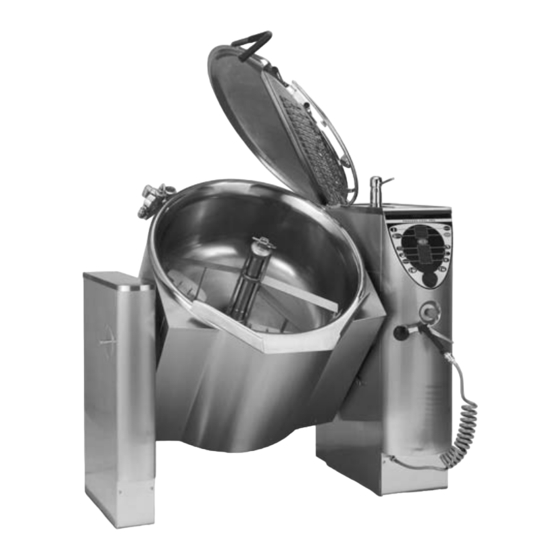
Page 14: Construction Of The Combi-Kettle
2.1.2009 Rev. 4.0 Safety instructions 2.2 Construction of the combi-kettle The main parts of the combi-kettle are illustrated in the following pictures: Support pillar Safety block Mixer and mixing tool (accessory) Strainer plate (accessory) Emptying valve for steam generator Safety lid Safety grid for fill opening One-grip tap for cleaning jet Control panel... - Page 15 2.1.2009 Rev. 4.0 Safety instructions Safety lid Lifting arm Locking lever of the lid Safety grid for fill opening Safety switch Cover for fill opening Control panel and mains switch Control panel Emergency/stop button Mains switch...
-
Page 16: Safe And Correct Use
2.1.2009 Rev. 4.0 Safety instructions Proveno Basic + AutoPack Heating HACCP Display for heating ON/OFF switch Error message lights Starting time Displays for timer and water fill Function time Automatic water fill Manual water fill Kettle bowl tilting Return kettle bowl to upright position Central dial 2.3 Safe and correct use Use of the combi-kettle is prohibited if you have not acquainted yourself with the user... -
Page 17: Avoiding Burns
2.1.2009 Rev. 4.0 Safety instructions 2.3.1 Avoiding burns • Beware of the inner surface, the upper rim and the lid that may be hot. • Beware of hot steam when opening the lid. • Beware of the hot mixing tool after cooking. Use protective gloves. •... -
Page 18: Changing The Settings And Adjustments
2.1.2009 Rev. 4.0 Safety instructions • Observe the cleaning instructions. Avoid excessive use of water when cleaning the control pillar. Use of a high-pressure jet is prohibited. Disconnect the control voltage of the kettle with the ON/OFF switch and with the mains switch before cleaning the kettle. -
Page 19: Safety Instructions In The Event Of Malfunction
2.1.2009 Rev. 4.0 Safety instructions 2.3.5 Safety instructions in the event of malfunction In case of a serious emergency, all functions of the appliance must be stopped by pressing the emergency/stop button or by turning the mains switch to the OFF position. The func- tions become operable when the button is released by turning it to the right. -
Page 20: Functional Description
2.1.2009 Rev. 4.0 Functional description 3. Functional description 3.1 Intended use of the appliance The Proveno combi-kettle is designed for professional food preparation. Using Proveno for other purposes is prohibited. It is forbidden to put corrosive ingredients or substances reacting with each other in the kettle. Please observe that long-term effect of some sub- stances used in food preparation is corrosive. -
Page 21: Operation Switches And Indicator Lights
2.1.2009 Rev. 4.0 Functional description 3.4 Operation switches and indicator lights All Proveno's operation switches, except for the central dial, are push buttons. The buttons are activated by a light and gentle push or by holding a button down for some time (2-10 seconds), depending on what function you plan to use. -
Page 22: Display Messages For The User
2.1.2009 Rev. 4.0 Functional description Proveno Basic + AutoPack Heating HACCP Display for heating ON/OFF switch Error message lights Starting time Displays for timer and water fill Function time Automatic water fill Manual water fill Kettle bowl tilting Return kettle bowl to upright position Central dial 3.4.1 Display messages for the user •... -
Page 23: Error Message Lights
2.1.2009 Rev. 4.0 Functional description 3.4.2 Error message lights There are two red indicator lights on the control panel to indicate an error or malfunction. Indicator light 1 Indicator light 2 Error/malfunction Indicator light 1 Indicator light 2 Low water level in steam generator illuminates illuminates Defective solenoid switch of the safety grid or the safety grid... -
Page 24: Operation Instructions
2.1.2009 Rev. 4.0 Operation instructions 4. Operation instructions 4.1 Before use 4.1.1 Preparing the use Daily check before use • Water supply (hot/cold) is open. • No inappropriate objects in the kettle. • Scrapers are correctly attached to the mixing tool. See "Positioning the mixing tool and scraper". - Page 25 2.1.2009 Rev. 4.0 Operation instructions • Also the pressure switch starts to function at 124°C (114°C) and informs about correct functioning by alternately blinking the red indicator lights inside the trian- gles (phase 3 tested). • After the pressure switch function has been checked, the heating is forced further until the safety valve opens.
- Page 26 2.1.2009 Rev. 4.0 Operation instructions Maintenance information Combi-kettle _________________ Serial No. __________________ Taken into use (date) __________________ Quarterly safety valve check performed Date Remarks Date Remarks Yearly maintenance performed Date Remarks Date Remarks Descaling performed Date Remarks Date Remarks...
-
Page 27: Operation Procedures
2.1.2009 Rev. 4.0 Operation instructions 4.2 Operation procedures 4.2.1 Operating the control panel - General When the appliance is started with the ON/OFF switch, all displays and indicator lights on the control panel illuminate for a short time (display test). After that, 'On' remains on the temperature display and the time on the timer display (if the kettle is fitted with a timer function). -
Page 28: Positioning The Mixing Tool And Scrapers
2.1.2009 Rev. 4.0 Operation instructions 4.2.3 Positioning the mixing tool and scrapers Attach the scrapers by placing the pins on the mixing tool into the holes on the scrapers. After that turn the scraper into place by lifting the scraper’s lower part. Finally pull the scraper forward. -
Page 29: Cooking
2.1.2009 Rev. 4.0 Operation instructions Then turn the handle aside. Make sure that the mixing tool is locked in its place by trying to lift/pull it out of its place by pulling at the mixer blade, for example. 4.2.4 Cooking Switch on the appliance. -
Page 30: Changing The Temperature
2.1.2009 Rev. 4.0 Operation instructions not manage to set the temperature while the temperature display was blinking, press the temperature button again and select the desired temperature with the central dial. Temperature setting and temperatures displayed: 0 - 50°C kettle inner surface temperature on the display 51 - 100°C food temperature on the display 101 - 120°C... - Page 31 2.1.2009 Rev. 4.0 Operation instructions Auto-reverse function When the mixer is running, press the mixer button once. A rotating symbol appears on the left-hand side of the display and the mixer is auto-reversing. Power mixing during mixing When the mixer is running, press and keep pressed the mixer button. A ro- tating symbol appears on the whole display.
-
Page 32: Mixing While Tilting (R Option)
2.1.2009 Rev. 4.0 Operation instructions Stopping the mixer program Press the stop button once. The mixer stops according to the instructions also if the lid is opened. The correct way to stop the mixer is to press the stop or start/pause button: Opening the lid activates the emergency/stop function. -
Page 33: Timer Functions
2.1.2009 Rev. 4.0 Operation instructions Automatic water fill Press once. Select the amount to be filled. Start filling by pressing once again. The selected amount of cold water flows automatically into the kettle. The display shows all the time the amount in litres poured into the kettle. Stopping/cancelling the automatic water fill Interrupt water fill by pressing once. - Page 34 2.1.2009 Rev. 4.0 Operation instructions Setting the date Setting the correct date is necessary to make the data collection possible. Press and simultaneously keep pressed. In about 2 seconds, the timer display starts blinking. Continue holding the button down until 'Yr' blinks on the timer display and two last digits of the year illuminate.
-
Page 35: Manual Cooling (Option)
2.1.2009 Rev. 4.0 Operation instructions Changing the timer-set cooking time Press once and select. Deactivating the activated/programmed timer Press and keep pressed for about 2 seconds. Deactivating the activated/programmed operation time Press and keep pressed for about 2 seconds. In case the starting time has not yet been reached, the starting time has to be deactivated by pressing the starting time button for about two seconds. -
Page 36: Possible Power Failure During Timing Or Easyrun Program
2.1.2009 Rev. 4.0 Operation instructions Spray gun hose Connector of emptying valve Emptying valve Drain valve Stopping the cooling • Close the cold water tap. • Detach the hand spray hose from the connector of the emptying valve. • Turn the drain valve to the cooking position. •... -
Page 37: Self-Control (Haccp) (Option)
2.1.2009 Rev. 4.0 Operation instructions • during operation time, letter E + interrupted time in hours and minutes and the re- maining operation time alternate on the display, e.g. E0.12 / r0.46, and the green indicator light on the operation time button is blinking •... -
Page 38: After Use
2.1.2009 Rev. 4.0 Operation instructions 4.3 After use 4.3.1 Cleaning Use of a high-pressure hose is forbidden. High-pressure hoses generate huge amounts of water fog that might contribute to contamination of food and food handling surfaces over large areas in the kitchen. Switch off the appliance with the ON/OFF switch or the mains switch before starting to wash the kettle. - Page 39 2.1.2009 Rev. 4.0 Operation instructions Wash the exterior of the appliance with running water only if necessary. Wiping with a damp cloth will often suffice. Consider the requirements of food hygiene when cleaning the kettle. Abundant use of water for soaking increases water consumption. However, if you want to clean the kettle by soaking, make use of the mixer to make soaking more ef- ficient, mixing slowly during soaking.
- Page 40 2.1.2009 Rev. 4.0 Operation instructions Refitting the lid parts Place the solid lid on the kettle approximately in the correct position. Pull the lifting arm down over the lid. Turn the solid lid so that the guiding pin lines up with the groove of the lifting arm.
-
Page 41: Periodic Service
2.1.2009 Rev. 4.0 Operation instructions 4.3.2 Periodic service Like a car, a food preparation appliance should be kept in good working order with the help of preventive maintenance. This guarantees trouble-free and safe operation of the ap- pliance. Depending on how much the kettle is used and in what kind of conditions it is operated, the technical condition of the Proveno combi-kettle should be checked accord- ing to plan from time to time. -
Page 42: Installation
2.1.2009 Rev. 4.0 Installation 5. Installation 5.1 General Please observe the instructions given in this chapter concerning the installation and ad- justments that must be done before taking the Proveno combi-kettle into use. Strict ob- servance of the instructions prevents malfunctions and damages potentially caused by defective installation. -
Page 43: Unpacking The Appliance
2.1.2009 Rev. 4.0 Installation • Protect the combi-kettle from sparks produced by welding, grinding and abrasive cutting wheels. These can later cause rust spots on the stainless steel surface of the appliance. 5.1.4 Unpacking the appliance The combi-kettle should be transported in its own package as close as possible to the in- stallation place before final unpacking. -
Page 44: Subsurface Frame Cast Into The Floor
2.1.2009 Rev. 4.0 Installation 5.2.1 Subsurface frame cast into the floor Installation frames are mounted according to the installation drawing, with the help of dis- tance guides supplied with the delivery. The frames must be installed in a horizontal po- sition and fixed so that they do not move during casting. -
Page 45: Surface Installation Frame Fixed To The Floor
2.1.2009 Rev. 4.0 Installation 5.2.2 Surface installation frame fixed to the floor Surface frames are mounted according to the installation drawing, with the help of dis- tance guides supplied with the delivery. If the inclination of the floor is very steep, it may be necessary to level the surface frame closer to the horizontal by placing stainless steel spacers between the frame and the floor. -
Page 46: Installing The Combi-Kettle On The Frame
2.1.2009 Rev. 4.0 Installation 5.2.3 Installing the combi-kettle on the frame The front and rear cover plates of the kettle's support and control pillar must be detached before installation. Each plate has been fixed at its lower edge with two screws. The rear plate of the control pillar has, in addition, two screws at the upper edge. - Page 47 2.1.2009 Rev. 4.0 Installation Support pillar Bearing unit Cover plate Mounting bracket for cover plate Washer + nut Washer + nut Installing the kettle section The kettle can be transferred from its transport pallet onto the installation frame in two different ways.
- Page 48 2.1.2009 Rev. 4.0 Installation The second alternative is to transfer the kettle by lifting the kettle section by its left-hand axle and by a lifting bar pushed through the control pillar. The lifting bar is positioned be- low the cross supports, located at the front and rear edge of the control pillar, slightly above the bearings.
- Page 49 2.1.2009 Rev. 4.0 Installation Gasket Lock ring Locking screw Next, the control pillar (1) is adjusted by means of the adjusting bolts (3), located on the corners, to a horizontal position and on the same level with the support pillar. When the control pillar (1) is in position, it is fixed to the installation frame (2) with four fixing bolts (4).
-
Page 50: Electrical Connections
2.1.2009 Rev. 4.0 Installation Installing the following kettle section If a kettle group is being installed, proceed as follows: Before installing the next kettle section, remove the bearing cover plate of the kettle al- ready installed. After this, install the bearing unit and the axle lead-through cover plate, supplied with the kettle delivery, exactly in the same way as it was installed on the support pillar. - Page 51 2.1.2009 Rev. 4.0 Installation If the control pillar front plate (1) is in place, it must be first detached by opening two screws (5) at the lower section of the plate. Detach the upper rear plate (3) by opening the two screws (5). The cable of the lid switch hinders the plate being detached entirely, but you can move the plate a little aside.
- Page 52 2.1.2009 Rev. 4.0 Installation Supply cable Lead-through plate Cable bushing Mains switch N and PE cables Cover plate Detach the cover plate (6) of the mains switch by pulling. Slip the supply cable (1) through the cable bushing (3) of the lead-through plate (2) (possibly detached) and upwards via the lead-through of the electrical box further to the mains switch (4), and connect the phase wires of the cable to the switch and N and PE cables (5) to the terminal blocks.
-
Page 53: Water Connections
2.1.2009 Rev. 4.0 Installation The correct rotation direction is anticlockwise viewed from the motor's cooling fan end. An arrow indicating the rotation direction is fixed to the motor on the same side where the connection box is located. If the rotation direction in two foregoing points is wrong, two phases of the supply cable coming to the mains switch have to be exchanged. -
Page 54: Optional Twin Water Connection (T) For Soft Water
2.1.2009 Rev. 4.0 Installation 5.4.2 Optional twin water connection (T) for soft water If fitted with a twin water connection this connection supplies softened water for filling of the kettle jacket, and if fitted with water-based cooling also for the cooling. 5.4.3 Extreme water conditions When extreme water conditions not fulfilling the requirements above exist, filters and wa- ter treatment devices should be installed in order to ensure proper function of the unit and... -
Page 55: Other Installations
2.1.2009 Rev. 4.0 Installation 5.6 Other installations In case the combi-kettle being installed is provided with a self-control option, and it is tak- en into use, the data cabling and the installation of the program must be carried out ac- cording to the instructions in the Help file of the "SafeTemp self-control"... -
Page 56: Fastening The Mixer Motor Cover Box
2.1.2009 Rev. 4.0 Installation Tilting lever Mounting plate of limit switches Limit switch for cooking position Limit switch of tilting end position Locking nut for adjustment Fixing nut for bearing unit and limit switch plate 5.7.2 Fastening the mixer motor cover box On the large kettle models (Proveno 150, 200, 300), the cover box of the mixing motor comes unattached inside the kettle. -
Page 57: Checking The Safety Block
2.1.2009 Rev. 4.0 Installation 5.8.2 Checking the safety block The Proveno combi-kettle is equipped with a four-phase safety block. Testing the block is performed in the way described below. NOTE: Values in brackets concern combi-kettle versions with a max. setting temperature of 110°C. It is not allowed to stand behind the kettle during the safety block check, because, when the check is completed, the safety valve at the kettle's rear edge opens, blowing hot steam out of the kettle. -
Page 58: Adjustments, Programming
2.1.2009 Rev. 4.0 Installation 5.9 Adjustments, programming The Proveno combi-kettle has been programmed in the factory with values suitable for the needs of professional kitchens. The combi-kettle is, however, provided with a "CSFP" technology (Customer Specific Function Parameters), which makes it possible to alter certain functions to better suit the specific needs of an individual customer or kitchen. -
Page 59: Adjustment Instructions
2.1.2009 Rev. 4.0 Adjustment instructions 6. Adjustment instructions 6.1 Setting customer specific parameters By setting the customer specific parameter it is possible to modify certain functions of the Proveno combi-kettle to better suit a kitchen’s or customer’s individual needs. In general, the preset factory settings are well suited to most users, so the settings need only be mod- ified to meet the special conditions or modes of operation in a kitchen. -
Page 60: Customer Specific Parameters, Settings And Factory Presets
2.1.2009 Rev. 4.0 Adjustment instructions Select a new parameter using the central dial and wait for 10 seconds, so the combi-kettle will revert to the standby mode. 6.2 Customer specific parameters, settings and factory presets The following table contains the parameter values starting from program revision Or54. The program revision is visible on the temperature display a short moment after switching the kettle on. - Page 61 2.1.2009 Rev. 4.0 Adjustment instructions Pr14 added 27.5.2002 (Or65) Pr15 added 27.5.2003 (Or71) Pr16 added 3.6.2003 (Or71) Pr41 added 15.9.2003 (Or73) Pr42 added 15.9.2003 (Or73)
-
Page 62: Troubleshooting
2.1.2009 Rev. 4.0 Troubleshooting 7. Troubleshooting MALFUNCTION POSSIBLE CAUSE WHAT TO DO The kettle cannot be The mains switch is in the OFF position Turn the mains switch fitted on the rear part of switched on the control pillar right side to the ON position The emergency/stop button is pushed Release the emergency-stop switch by turning it clockwise... - Page 63 2.1.2009 Rev. 4.0 Troubleshooting The kettle does not tilt The lid of the kettle is on and the mixer display Open the lid shows a 'Lid' signal The emergency/stop button is pushed Release the emergency-stop switch by turning it clockwise The ON/OFF switch is not in the ON position Push the switch to the ON position Other technical fault...
- Page 64 2.1.2009 Rev. 4.0 Troubleshooting When you contact service personnel, give the following information for the unit in ques- tion: • what is the type and model of the unit • what is the serial number of the unit and the date the unit has been installed •...
-
Page 65: Technical Specifications
2.1.2009 Rev. 4.0 Technical specifications Technical specifications Connection diagram S00123 B3 Installation drawing L00091 G3 Text part L00103 C3... - Page 66 Connection diagram S00123 B3...
- Page 67 Installation drawing L00091 G3...
- Page 68 Text part L00103 C3...
- Page 69 2.1.2009 Rev. 4.0 Technical specifications Item Type Accessory Specification Overall dimensions incl. support pillar 40,60 1037x800x900/1150 mm WxDxH Overall dimensions incl. support pillar 80,100 1144x800x900/1150 mm WxDxH Overall dimensions incl. support pillar 150,200 1350x920x900/1150 mm WxDxH Overall dimensions incl. support pillar 1550x1160x900/1150 mm WxDxH Support pillar dimensions LxDxH...
- Page 70 2.1.2009 Rev. 4.0 Technical specifications Item Type Accessory Specification Weight 534 kg Transport volume 40,60 1,32 Transport volume 80,100 1,45 Transport volume 150,200 2,01 Transport volume 2,73 Mixer power 40,60,80,100 M,MC3P,MC4P 0,75 kW Mixer power 150,200,300 M,MC3P,MC4P 1,5 kW Electricity connections see Wiring diagram Water connections see Installation drawing...
Need help?
Do you have a question about the PROVENO E 100 l and is the answer not in the manual?
Questions and answers