Table of Contents
Advertisement
Quick Links
Advertisement
Table of Contents

Related Manuals for Metos DOMITOR


Summary of Contents for Metos DOMITOR
- Page 1 PIZZA OVEN DOMITOR Installation and Operation Manual...
-
Page 3: Table Of Contents
ENGLISH CHAPTER CHAPTER ........................ Chapter for the technician and operator Chapter for the technician and operator 1.1 GENERAL WARNINGS ........Page GB-3 6.1 ROUTINE AND PLANNED MAINTENANCE ..Page GB-22 1.2 REFERENCE NORMATIVE ......... Page GB-4 6.1.a In general ..........Page GB-22 1.3 DESCRIPTION OF THE SYMBOLS ..... -
Page 5: General Warnings
DOMITOR DM/DB General specifi cations and warning Chapter 1 1.1 - GENERAL WARNINGS - The oven shall not be left unguarded. - Wear safety clothing only, approved by the law in force. - Before starting the oven, user shall carefully read this han- dbook and be aware of both technical specifi... -
Page 6: Reference Normative
DOMITOR DM/DB General specifi cations and warning - THESE SAFETY REGULATIONS INTEGRATE OR COM- PLEMENT THE LOCAL SAFETY REGULATIONS. - NEVER carry out hasty or makeshift repairs which could jeopardize the oven functioning and user’s safety, as ATTENTION well. This symbol is used in the safety messages of the... -
Page 7: Prearrangements At Purchaser'scharge
1.8 - ACOUSTIC PRESSURE LEVEL • It is necessary to prearrange a vapour fl ue, whose With DOMITOR ovens, an A acoustic continuous equi- features shall be in compliance with the rules being in valent weighted pressure level(dB) under the maximum force in the Country the oven shall be installed in. -
Page 8: Overall Dimensions
DOMITOR DM/DB Technical data - Transport and unpacking Chapter 2 OVERALL DIMENSIONS 430 - 435 630S - 630L 635S - 635L 930 - 935 830 - 835 1230S - 1230L 1235S - 1235L H= neutral hood H1= motor-driven hodd height sizes in mm Mod. -
Page 9: Technical Features
DOMITOR DM/DB Technical data - Transport and unpacking 2.1 - TECHNICAL FEATURES Model Power Electric Cable Relative kW/max connection section temperature humidity 230V-3 4x2,5 400°C 10 ÷ 80 % 400V-3 N 5x2,5 400°C 630S 230V-3 4x2,5 400°C 10 ÷ 80 %... - Page 10 DOMITOR DM/DB Technical data - Transport and unpacking Model. Ceiling Bedplate Code resistance resistance Power N° W.CAD N° W.CAD DM430 1 Camera 2200 1 Camera 2200 2 Camere 2200 2 Camere 2200 EE28200 3 Camere 2200 3 Camere 2200 13,2...
-
Page 11: Transport
DOMITOR DM/DB Technical data - Transport and unpacking 2.2 - TRANSPORT FIG. 1 FIG. 1 2.2.a - Shipment (Fig. 1) The oven is positioned on a wooden pallet, inside a strapped cardboard box. The shipment of the oven shall be carried out by... -
Page 12: Reception Of The Machine
DOMITOR DM/DB Technical data - Transport and unpacking 2.3 - RECEPTION OF THE MACHINE FIG. 3 Upon reception of the machine make sure that the packing is complete and not damaged. Should the packing be complete, remove it as specify at point 2.4 (aside from different manufacturer’s instructions). -
Page 13: Identification Of The Components
DOMITOR DM/DB Technical data - Transport and unpacking 2.5 - IDENTIFICATION OF THE COMPONENTS 2.6 - OVEN IDENTIFICATION (Fig 4) Oven serial number and identifi cation data are reported (Fig. 4) on a plate (7) being fi xed on the oven base. -
Page 14: Oven Lifting
DOMITOR DM/DB Installation and connections Chapter 3 FIG. 1 DANGER All operations described in this chapter shall be carried out by skilled and authorized technicians, only. 3.1 - OVEN LIFTING (Fig 1) The oven lifting shall be carried out by using a crane or a tackle as follows: •... - Page 15 DOMITOR DM/DB Installation and connections FIG. 3 Two-, three-chamber oven assembling (Fig 3) (For 430-435 models, only) • To assemble the two-chamber oven, position the second oven (7) the fi rst oven (6) and fi x it by the small bracket (8) and the screws (9).
-
Page 16: Electrical Connection
DOMITOR DM/DB Technical data - Transport and unpacking FIG. 6 3.3 - ELECTRICAL CONNECTION (Fig. 6) DANGER • The power feed line should be provided with a suitable omnipolar DISCONNECTING SWITCH (automatic thermomagnetic switch or differential) placed before the control unit main switch, with a minimum contact opening of 3 mm. -
Page 17: Unipotential Connection
DOMITOR DM/DB Installation and connections FIG. 7 3.3.b - Electric hood connection Concerning electric hood connection, follow the instruc- tions supplied with the hood. 3.3.c - Unipotential connection (Fig 7) The equipment shall be inserted in a unipotential system, whose effectiveness shall be verifi ed according to the rules being in force. -
Page 18: Type Of Use And
4.1 - TYPE OF USE AND CONTRAINDICA- FIG. 1 TIONS IMPORTANT DOMITOR DM/DB ovens are professional machines suitable for baking pizza and similar products. The various models shall only be used to process as above; in case of any other use, manufacturer... -
Page 19: User's Areas
DOMITOR DM/DB Safety devices FIG. 2 4.3 - SAFETY DEVICES (Fig 2) The equipment is equipped with following safety sy- stems: 1) All dangerous areas are closed by screwed cases. 2) Each oven is equipped under the right-hand panel with a safety thermostat (1) to allow the oven to be disconnected in case of overtemperature inside the baking chamber. -
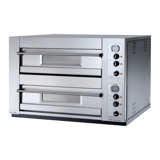
Page 20: Oven Control Board
DOMITOR DM/DB Functioning Capitolo 5 5.1 - OVEN CONTROL BOARD (Fig 1) FIG. 1 On the oven, there are the following control elements: 1. Line selector switch ON/OFF 4. Crown plate temperature adjustment thermo- If you turn it onto ON, it energizes the control ele-... -
Page 21: Oven Preparation
DOMITOR DM/DB Functioning 5.2 - OVEN PREPARATION FIG. 2 Pizza can be baked either directly on the refractory oven surface or in the baking-tin. Here below you can fi nd some instructions to adjust the different parameters. IMPORTANT When you are going to start the oven, do not adjust cei- ling and bedplate resistances at their maximum capacity, since the oven temperature would in such a case be 50°... -
Page 22: Pizza Baking
DOMITOR DM/DB Functioning 5.3 - PIZZA BAKING FIG. 3 • As soon as the set temperature value is reached, open the access door and insert the pizza to be baked. ATTENTION Inside the oven, temperature is very high, therefore suitable individual protection means shall be used to insert and remove the pizza;... -
Page 23: Malfuctioning,Cause And Cure
DOMITOR DM/DB Functioning 5.6 - MALFUCTIONING,CAUSE AND CURE FIG. 4 The oven does not start: • Verify the electric connection. • Make sure the cutout switch is on. • Contact manufacturer’s technical service. Pizza is not baked, uniformly: • The baking surface is dirt: clean the baking surface •... -
Page 24: Routine And Planned Maintenance
DOMITOR DM/DB Maintenance Chapter 6 6.1 - ROUTINE AND PLANNED MAINTENANCE 6.1.b - Ordinary maintenance 6.1.b.a - Outer cleaning (to be carried out every day) 6.1.a- In general ATTENTION DANGER At the end of each working cycle, carefully clean the oven. -
Page 25: C - A Every 600 Hours A Careful Chamber Cleaning
DOMITOR DM/DB Maintenance 6.1.c - Planned maintenance FIG. 2 6.1.c.a - Every 600 hours a careful chamber cleaning (Fig 2) • Make sure the oven is totally cool, then open the door, remove the protection (1) unscrewing the relevant screws and gently take off the refractory surface (2) from the door. -
Page 26: D - C Ceiling Or Bedplate Resistance Replacement
DOMITOR DM/DB Maintenance 6.1.d.b - Lamp replacement (Fig 4) FIG. 4 • Unscrew the glass (1) protecting the lamp (2). • Unscrew theburnt out lamp (2) and replace it, then reassemble all by proceeding in the opposite way. 6.1.d.c - Ceiling or bedplate resistance replacement FIG. -
Page 27: D - D Door Spring Replacement
DOMITOR DM/DB Maintenance FIG. 6 6.1.d.d - Door spring replacement (Fig 6) DANGER This operation shall be carried out by skilled tech- nicians. • Remove the right-hand panel (1) by unscrewing the relevant screws. • Remove the control board (2) by unscrewing the relevant screws. - Page 28 DOMITOR DM/DB Maintenance FIG. 7 6.1.d.e - Door pane replacement (Fig 7) DANGER This operation shall be carried out by skilled tech- nicians. • Open the door (1) and remove the inner panel (2) loosening the relevant screws (3). •...
-
Page 29: Oven Disassembly
DOMITOR DM/DB Dismantling - Demolition - Disposal Chapter 7 7.1 - OVEN DISASSEMBLY In case the oven shall be disassembled to reinstall it later, ATTENTION proceed in a reverse order compared to the description Consult the next paragraph when disposing of being reported in “Installation”... -
Page 30: Wiring Diagram Dm 430-435 V400 Trifase
DOMITOR DM/DB Wiring diagram WIRING DIAGRAM DM 430-435 V400 Trifase YW-GN 230V-40W GB - 28... -
Page 31: Wiring Diagram Dm 430-435 V230 Single-Phase
DOMITOR DM/DB Wiring diagram WIRING DIAGRAM DM 430-435 V230 Single-phase YW-GN 230V-40W GB - 29... -
Page 32: Wiring Diagram Dm 430-435 V230 Trifase
DOMITOR DM/DB Wiring diagram WIRING DIAGRAM DM 430-435 V230 Trifase YW-GN 230V-40W GB - 30... -
Page 33: Wiring Diagram Dm 630-635 V400 Trifase
DOMITOR DM/DB Wiring diagram WIRING DIAGRAM DM 630-635 V400 Trifase GB - 31... -
Page 34: Wiring Diagram Dm 630-635-930-935 V230 Trifase
DOMITOR DM/DB Wiring diagram WIRING DIAGRAM DM 630-635-930-935 V230 Trifase GB - 32... -
Page 35: Wiring Diagram Db 830-835 V400 Trifase
DOMITOR DM/DB Wiring diagram WIRING DIAGRAM DB 830-835 V400 Trifase YW-GN 230V-40W 230V-40W GB - 33... -
Page 36: Wiring Diagram Db 830-835 V230 Trifase
DOMITOR DM/DB Wiring diagram WIRING DIAGRAM DB 830-835 V230 Trifase YW-GN 230V-40W 230V-40W GB - 34... -
Page 37: Wiring Diagram Db 1230-1235 V230 Trifase
DOMITOR DM/DB Wiring diagram WIRING DIAGRAM DB 1230-1235 V230 Trifase GB - 35... -
Page 38: Wiring Diagram Db 1230-1235 V400 Trifase
DOMITOR DM/DB Wiring diagram WIRING DIAGRAM DM 1230-1235 V400 Trifase GB - 36... -
Page 39: Oven Caption 430-435 V400/230
DOMITOR DM/DB Wiring diagram OVEN CAPTION 430-435 V400/230 EL1 = Led ON/OFF EL2 = Lamp EL3 = Upper thermostat led globe EL4 = Bottom plane thermostat led globe F = Antijamming device KM = Contactor Q = Main switch R1 = Upper resistance... -
Page 40: Oven Caption 830-835 V400/230
DOMITOR DM/DB Wiring diagram OVEN CAPTION 830-835 V400/230 UPPER ROOM EL1 = Led ON/OFF EL2 = Lamp EL3 = Upper thermostat led globe EL4 = Bottom plane thermostat led globe F1 = Antijamming device KM1 = Contactor Q1 = Main switch... -
Page 41: Oven Caption 1230-1235 V400/230
DOMITOR DM/DB Wiring diagram OVEN CAPTION 1230-1235 V400/230 UPPER ROOM EL1 = Led ON/OFF EL2 = Lamp EL3 = Upper thermostat led globe EL4 = Bottom plane thermostat led globe F = Antijamming device KM1 = Upper contactor KM2 = Bottom contactor...