
Related Manuals for Pfeiffer Vacuum TC 400 E74


Summary of Contents for Pfeiffer Vacuum TC 400 E74
- Page 1 OPERATING INSTRUCTIONS Translation of the original instructions TC 400 E74 Electronic Drive Unit...
-
Page 2: Table Of Contents
6.3 Cross-linking via the connection RS-485 ......12 The Pfeiffer Vacuum parameter set ....... . 13 7.1 General . -
Page 3: About This Manual
About this manual Validity This operating manual is for customers of Pfeiffer Vacuum. It describes the functioning of the designated product and provides the most important information for safe use of the unit. The description follows applicable EU guidelines. All information provided in this operating manual refers to the current state of the product's development. - Page 4 About this manual Pictographs Prohibition of an action to avoid any risk of accidents, the disregarding of which may result in serious accidents Warning of a displayed source of danger in connection with operation of the unit or equipment Command to perform an action or task associated with a source of dan- ger, the disregarding of which may result in serious accidents Important information about the product or this document ...
-
Page 5: Safety
● Power supply: The turbopump power supply must apply to the requirements of dou- ble insulation between mains input voltage and operating voltage according to the reg- ulations of IEC 61010 and IEC 60950. Therefore Pfeiffer Vacuum recommends to use exclusively original-power packs and -accessories. Only in this case Pfeiffer Vacuum is able to guarantee the compliance of the European and North American guidelines. -
Page 6: Proper Use
Following installation into a plant and before commissioning, the operator must check the entire system for compliance with the valid EU directives and reassess it accord- ingly. ● The electronic drive unit TC 400 E74 operates designated Pfeiffer Vacuum turbo- pumps and their accessories. Improper use Improper use will cause all claims for liability and warranties to be forfeited. -
Page 7: Product Description
For information about other certifications, if applicable, please see the signet on the prod- uct or: ● www.tuvdotcom.com ● TUVdotCOM-ID 0000021320 The electronic drive unit TC 400 E74 is an integrated component of the turbopump. It's Product characteris- purpose is to drive, monitor and control the entire pump. tics... -
Page 8: Function
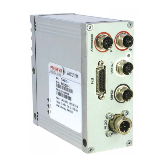
SEMI E74. RS-485 M12 socket with screw coupling for the connection of a Pfeiffer Vacuum control unit or a PC. The use of a Y-connector enables the series connection in a bus system. Casing socket on the rear side of the electronic drive unit for the connection to the turbopump. -
Page 9: Connection Diagram
4 ... 27 V DC Imax = 100 mA 4 ... 27 V DC Pin 3 ... 8 Pin 3 ... 8 Pin 11 ... 15 Pin 11 ... 15 Fig. 3: Connection diagram and assignment of the TC 400 E74... -
Page 10: Connection "E74
Connection "E74" Connection "E74" The connection "E74" on the TC 400 E74 with 15-pole female plug contains besides the signals, described in the SEMI E74-0301 standard, an additional inverted alarm signal and an analog output. Input signal Output signal signal (+) -
Page 11: Connection "Rs-485
Connection "RS-485" Connections A Pfeiffer Vacuum display and control panel (DCU or HPU) or an external PC can be connected to the electronic drive unit via the connection designated "RS-485". The inter- face is electrically isolated from the maximum supply voltage of the electronic drive unit. -
Page 12: Cross-Linking Via The Connection Rs-485
Connection "RS-485" Cross-linking via the connection RS-485 USB/RS-485-converter USB/RS-485-converter TC/TM TC/TM RS 485 RJ45 TC 600 / 750 CAUTION Danger of electric shock The insulation measures of the bus system are designed only for use with safety extra- low voltage. ... -
Page 13: The Pfeiffer Vacuum Parameter Set
All function-relevant variables of a turbopump are anchored in the electronic drive unit as parameters. Each parameter has a three-digit number and a designation. Parameters can be used via Pfeiffer Vacuum display and control units or via RS-485 with the Pfeiffer Vacuum protocol. - Page 14 The Pfeiffer Vacuum parameter set Control commands default Display Designation Functions Unit min max 001 Heating Heating 0 = off 1 = on 002 Standby Standby 0 = off 1 = on 004 RUTimeCtrl Run-up time control 0 = off...
- Page 15 The Pfeiffer Vacuum parameter set Status requests default Display Designation Functions Unit min max RemotePrio Remote priority 0 = no 1 = yes SpdSwPtAtt Rotation speed switchpoint attained 0 = no 1 = yes Error code Error code OvTempElec...
-
Page 16: Configuring The Connections
1,5 - 8,5 V for sensor RPT p (hPa) = 10 (U-10.5 V) 1,5 - 8,5 V for sensor IKT p (hPa) = 10 9 V: overrange 8 = Control fore-vacuum Fore-vacuum signal; control of Pfeiffer Vacuum turbo pumping stations... -
Page 17: Operation With The Pfeiffer Vacuum Parameter Set
Ensure the gas mode is correctly set. Contact Pfeiffer Vacuum before using gases with a greater molecular mass (> 80). ● Gas mode "0" for gases with the molecular mass >39, e.g. argon. ● Gas mode "1" for gases with the molecular mass 39. - Page 18 The Pfeiffer Vacuum parameter set Adjust the parameter [P:708] to the desired value in %. Set value power con- sumption If adjusting the set value power consumption below 100 % the run-up time prolongs. To avoid error messages, the parameter [P:700] RUTimeSVal should be adjusted accord- ingly.
- Page 19 The Pfeiffer Vacuum parameter set [P:017] = 1 [P:701] [P:719] [P:010] [P:302] Process Fig. 7: Example for the configuration rotation speed switchpoint 1+2 active; [P:701] > [P:719] [P:017] = 1 [P:719] [P:701] [P:010] [P:302] Process Fig. 8: Example for the configuration rotation speed switchpoints 1+2 active; [P:701] < [P:719]...
- Page 20 Pfeiffer Vacuum recommends the intermittend mode between 5 and 10 hPa. A pressure gauge and a dosing valve are required to set the switching thresholds.
- Page 21 The Pfeiffer Vacuum parameter set Adjust the switch off threshold backing pump via parameter [P:710] to the determined drive power for a fore-vacuum pressure of 5 hPa. Delayed switching on Switching on the turbopump and the backing pump at the same time can result in un- wanted gas flows.
-
Page 22: Switching On/Off The Pump
The Pfeiffer Vacuum parameter set Direct venting Start and venting time are not configurable. Venting starts with a delay of 6 s after "pump- ing station off". When the function "pumping station" is switched on renewed, the venting valve closes automatically. In the event of a power failure, venting will occur if an an- chored type-specific rotation speed is underrun. -
Page 23: Pfeiffer Vacuum Protocol For "Rs-485
Pfeiffer Vacuum Protocol for "RS-485" Pfeiffer Vacuum Protocol for "RS-485" Telegram frame The telegram frame of the Pfeiffer Vacuum protocol contains only ASCII code characters [32; 127], the exception being the end character of the message . Basically, a master ... -
Page 24: Applied Data Types
Pfeiffer Vacuum Protocol for "RS-485" Example 2 Control command Switch on pumping station (parameter [P:010], device address slave: "042") ! ASCII Control command understood Switch on pumping station (parameter [P:010], device address slave: "042") ! ASCII Applied data types Datentyp Beschreibung Länge l1 - l0... -
Page 25: Malfunctions
Error Problem Possible causes Remedy code Err001 Overspeed Call Pfeiffer Vacuum Service Only acknowledge for rotational speed f = 0 Err002 Overvoltage – Incorrect power pack used Check power pack type Check partial mains voltage Err006 Run-up fault –... - Page 26 Possible causes Remedy code Err010 Internal device error Call Pfeiffer Vacuum Service Only acknowledge for rotational speed f = 0 Err021 Drive electronics fail to identify pump Call Pfeiffer Vacuum Service Only acknowledge for rotational speed f = 0...
- Page 27 Malfunctions Error Problem Possible causes Remedy code Wrn116 Temperature evaluation on bearings is Call Pfeiffer Vacuum Service faulty Wrn117 High pump base temperature – Insufficient cooling Improve cooling Check deployment conditions Wrn118 High output stage temperature – Insufficient cooling ...
-
Page 28: Declaration Of Conformity
EC directives: ● Electromagnetic Compatibility 2014/30/EU ● Low Voltage 2014/35/EU ● Restriction of the use of certain Hazardous Substances 2011/65/EU TC 400 E74 Harmonised standards and national standards and specifications which have been ap- plied: DIN EN 61000-3-2 : 2014... - Page 29 VACUUM SOLUTIONS FROM A SINGLE SOURCE Pfeiffer Vacuum stands for innovative and custom vacuum solutions worldwide, technological perfection, competent advice and reliable service. COMPLETE RANGE OF PRODUCTS From a single component to complex systems: We are the only supplier of vacuum technology that provides a complete product portfolio.
Need help?
Do you have a question about the TC 400 E74 and is the answer not in the manual?
Questions and answers