
Related Manuals for Pfeiffer Vacuum OBC V4


Summary of Contents for Pfeiffer Vacuum OBC V4
- Page 1 OPERATING INSTRUCTIONS Translation of the Original OBC V4 Electronic drive unit...
- Page 2 These operating instructions describe all models and variants of your product. Note that your product may not be equipped with all features described in this document. Pfeiffer Vacuum constantly adapts its products to the latest state of the art without prior notice. Please take into account that online operating instructions can deviate from the printed operating instructions supplied with your product.
-
Page 3: Table Of Contents
Table of contents Table of contents About this manual Validity 1.1.1 Applicable documents 1.1.2 Products concerned Target group Conventions 1.3.1 Instructions in the text 1.3.2 Pictographs 1.3.3 Labels 1.3.4 Abbreviations Trademark proof Safety General safety information Safety instructions Precautions Intended use Misuse Transportation and Storage Receipt of the product... - Page 4 Decommissioning 10.1 Shutting down for longer periods 10.2 Recommissioning 10.3 Disposal Malfunctions 11.1 Malfunction and fault indication 11.2 Malfunction Service solutions by Pfeiffer Vacuum Accessories Spare parts Technical data and dimensions 15.1 Technical data 15.2 Environmental conditions 15.3 Electrical characteristics 15.4 Cooling water characteristics...
- Page 5 List of tables List of tables Tbl. 1: Meaning of LED on the control panel Tbl. 2: Description of the HHR's keys Tbl. 3: OBC V4 spare parts Tbl. 4: Electrical characteristics of the customer’s network Tbl. 5: Cooling water characteristics 5/60...
- Page 6 Fig. 5: Pumping installation diagram Fig. 6: Remote connector: control by direct voltage Fig. 7: Remote connector: control by dry contacts Fig. 8: Remote connector: logic outputs Fig. 9: Draining the water circuit Fig. 10: Dimensions - OBC V4 6/60...
-
Page 7: About This Manual
Keep the manual for future consultation. 1.1 Validity This operating instructions is a customer document of Pfeiffer Vacuum. The operating instructions de- scribe the functions of the named product and provide the most important information for the safe use of the device. The description is written in accordance with the valid directives. The information in this op- erating instructions refers to the product's current development status. -
Page 8: Conventions
About this manual 1.3 Conventions 1.3.1 Instructions in the text Usage instructions in the document follow a general structure that is complete in itself. The required ac- tion is indicated by an individual step or multi-part action steps. Individual action step A horizontal, solid triangle indicates the only step in an action. ►... -
Page 9: Abbreviations
About this manual This label warns users that they risk being injured if their hands come into contact with a hot surface: wear protective gloves before any intervention. This label indicates that certain internal components carry an electric charge and can cause electric shock if touched: before working on the pump, always either disconnect it, or lock out/tag out the installation breaker in the appro- priate manner. -
Page 10: Safety
Safety 2 Safety 2.1 General safety information The following 4 risk levels and 1 information level are taken into account in this document. DANGER Immediately pending danger Indicates an immediately pending danger that will result in death or serious injury if not observed. ►... -
Page 11: Precautions
Safety WARNING Risk of electric shock due to non-compliant electrical installations This product uses mains voltage for its power supply. Non-compliant electrical installations or installa- tions not done to professional standards may endanger the user’s life. ► Only qualified technicians trained in the relevant electrical safety and EMC regulations are au- thorized to work on the electrical installation. -
Page 12: Intended Use
► Regularly check compliance with all precautionary measures. 2.4 Intended use ● The OBC electronic drive unit is used to operate Pfeiffer Vacuum magnetically levitated turbomo- lecular pumps (see chapter “Products Concerned”). ● The OBC electronic drive unit installed on the magnetically levitated pump is designed to be inte- grated into industrial equipment. -
Page 13: Transportation And Storage
Transportation and Storage 3 Transportation and Storage 3.1 Receipt of the product Condition of the delivery ● Check that the product has not been damaged during transport. ● If the product is damaged, take the necessary measures with the carrier and notify the manufacturer. -
Page 14: Stockage
3.3 Stockage Storing the new electronic drive unit Pfeiffer Vacuum recommends storing the product in its original packaging to keep it clean. 1. Keep the pump wrapped in its protective envelope. 2. Store the electronic drive unit in line with the permitted storage temperatures (see chapter “Envi- ronmental conditions”). -
Page 15: Product Description
Product description 4 Product description 4.1 Product identification To correctly identify the product when communicating with our service center, always have the informa- tion from the product rating plate available (see chapter "Labels"). 4.1.1 Scope of delivery ● 1 electronic drive unit ● 1 mains socket ●... -
Page 16: Man/Machine Interface
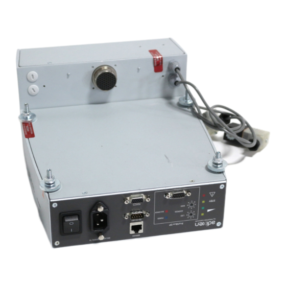
RS 232/485 AC in 200-240VAC 50/60 Hz 7A remote Fig. 1: OBC V4 Description 1. Pump operating status indicator light 2. Fieldbus connection area 3. Hand held remote control connector (Service) 4. Remote control connector (Remote) 5. RS-232/RS-485 serial link connector 6. -
Page 17: Installation
Installation 5 Installation Depending on the ordering guide, on delivery, the electronic drive unit may be: ► installed on the magnetically levitated pump: in this case, install the pump in the equipment (see chapter Installation of the pump operating instructions). ► supplied separately: in this case, connect it to the pump and then install the pump in the equip- ment (see chapter Installation of the pump operating instructions). -
Page 18: Positioning The Equipped Pump On The Installation
Installation 6. Adjust the module position with the other thumb-wheels so that the module is parallel to the fas- tening plate (step E). 7. Screw the 2 screws to lock the module position on the fastening plate (screws on the fastening plate) (step F). -
Page 19: Procedure For Assembly Connectors
Installation NOTICE The water cooling circuit may be damaged if an unregulated mains supply is used Using unregulated mains water can lead to water circuit clogging due to limescale deposition. This may necessitate complete cleaning and overhaul of the water cooling circuit. Furthermore, the presence of micro-organisms such as algae and biological substances such as bacteria can lead to cooling problems in the pump. -
Page 20: Connecting The Pump To The Water Circuit
Installation 3. Manually place the nut into contact. 4. Tighten the nut 1/2 turn using an open-ended spanner while holding the body of the connec- tor still. 5.3.2 Connecting the pump to the water circuit Water-cooling circuit connection M version of pump with OBC MT version of pump with OBC M version of pump with lateral OBC 1. -
Page 21: Customer Electrical Installation Protection
Installation WARNING Danger of electrocution by contact during maintenance or overhaul There is an electric shock hazard in case of contact with a product powered on and not electrically isolated. ► Before carrying out any work, set the main switch to O. ►... -
Page 22: Mains Connection By Electrical Connector
Installation Absence of emergency stop The vacuum pump is not equipped with an emergency stop device (EMS) or a lock-out de- vice. The vacuum pump is designed to be integrated into equipment fitted with an emer- gency stop device. ● When activated, the EMS of the equipment must switch off the vacuum pump. Operation in local mode There is no device to warn that the pump is operating in local mode. -
Page 23: Mains Connection By A Stuffing Box
Installation 5.4.3 Mains connection by a stuffing box WARNING Danger to life from electric shock in the event of a fault In the event of a fault, devices connected to the mains may be live. There is a danger to life from electric shock when making contact with live components. - Page 24 Installation Turbo Heating/Braking Venting Purge Water 24VDC Water Fig. 4: Typical electrical wiring diagram Heater band power supply (MT version pump) Magnetically levitated turbomolecular pump Water valve power supply (MT version pump) Electronic drive unit Backing pump Inert gas input Fore-vacuum isolation valve High vacuum isolation valve Purge solenoid valve (option)
-
Page 25: Operation
Operation 6 Operation 6.1 Preliminary precautions for use WARNING Risk of electric shock in the event of electrical disconnection while the pump is running The turbomolecular pump and its electronic drive unit cannot be disconnected from the electrical net- work before the rotor completely stops rotating: the pump/electronic drive unit must be isolated from the electrical network to prevent electric shock! 1. -
Page 26: Restarting The Pump After An Emergency Equipment Stop
Operation Components in the pumping installation Fore vacuum isolation valve Inert gas purge inlet High vacuum isolation valve Turbo Magnetically levitated turbomolecular pump Purge solenoid valve (option) Backing pump Air inlet solenoid valve (accessory) 1) The supply, power supply and control of these components are the customer’s responsibility. 2) These solenoid valves are controlled via the electronic drive unit. -
Page 27: Shutting Down The Pump
Operation 6.3 Shutting down the pump 6.3.1 Pumping shutdown NOTICE Risk of damaging the pump by generating an electric arc The pump and its electronic drive unit must not be disconnected from the electrical network before the rotor completely stops rotating and the unit is isolated from the electrical network: an electric arc is created when the circuit is interrupted, which damages internal components. -
Page 28: Powering Off
Operation When a power failure occurs, the rotor remains suspended by the energy emitted by the motor’s coun- ter-electromotive force, until the rotor rotation speed is low enough that it can rest on the landing bear- ings without being damaged. If the power is restored before the minimum speed is reached, the pump recovers its initial speed with- out any disturbance. -
Page 29: Advanced Settings
The integrated heater band heats the pump to an adjustable temperature (refered to as temperature setpoint) to prevent the effects of condensation. The temperature setpoint depends on the application the pump is to be used for. Contact Pfeiffer Vacuum’s applications department for advice in choosing the correct temperature setpoint. -
Page 30: Interfaces For Control
Interfaces for control 8 Interfaces for control 8.1 Control modes This chapter describes the connections and protocols associated with each control mode. There are 4 control modes: ● HHR The pump is controlled locally from a Hand-Held Remote control (HHR), connected on the SERV- ICE connector. -
Page 31: Powering On
Interfaces for control Functions Functions ● To move to the next or previous menu, next or ● To start the pump in local mode via HHR when START previous parameter in the displayed menu. the [SET UP][REMOTE CONTROL] menu is [KEYBOARD] (see chapter 'Menu SETUP'). -
Page 32: Display Menu
Interfaces for control Display initialization The electronic drive unit performs a self-test and identifies the connected pump. ■■■■■■■■■■■■■■■■■■■■■ Boot-up time is approximately 15 seconds. ■■■■■■■■■■■■■■■■■■■■■ ■■■■■■■■■■■■■■■■■■■■■ ■■■■■■■■■■■■■■■■■■■■■ ■■■■■■■■■■■■■■■■■■■■■ ■■■■■■■■■■■■■■■■■■■■■ The equipment is identified, the software release is displayed, and communication with the pump is tested. -
Page 33: Setup Menu
Interfaces for control 8.2.3 SETUP menu Selection Choice Description Initial setting ACCESS CODE 0 to 65535 REMOTE CONTROL KEYBOARD Choose the interface control mode. According to ordering guide. REMOTE HARD SERIAL LINK LONWORKS DEVICENET PROFIBUS ETHERCAT STAND-BY SPEED Activate pump Stand-by speed (select- 15000 from 15000 min to pump... -
Page 34: Control Via The Remote Connector
Interfaces for control 8.3 Control via the REMOTE connector NOTICE Safety of Extra-Low Voltage circuits Remote control circuits are equipped with dry contact outputs (24 V - 1 A max). Overvoltages and overcurrents can result in internal electrical damage. Users must observe the following wiring condi- tions: ►... -
Page 35: Logic Output Wiring
Interfaces for control Control by dry contacts To control these inputs by external contacts of the host equipment, connect pins 10 with 15 and wire the used contacts (wiring customer supplied). Pins 11, 12, 13, 14 are connected to + 15 V (pin 5) to be ac- tive. -
Page 36: Command Via The Rs-232/Rs-485 Serial Link
Interfaces for control Contact Function OK for process Contact closed: OK for Process – M version : speed ≥ nominal speed (set by ‘Relay At Speed’ parameter), (see chapter “SETUP menu”), (see chapter “List of commands”). – MT version : speed ≥ nominal speed (set by ‘Relay At Speed’ parameter), (see chapter “SETUP menu”), (see chapter “List of commands”);... -
Page 37: Communication Protocol
Interfaces for control Assignment Data reception (RS-232) Data transmission (RS-232) RS-485: V- RS-485: V+ The user must use shielded links and connections in compliance with EMC and electrical safety stand- ards. RS-232 connection A computer manages a single pump (P1) using the RS-232 link via the RS-232/RS-485 connector. RS-485 connection A computer manages several pumps (P1, P2, Pn, etc.) using a RS-485 serial link via the RS-232/ RS-485 connector. -
Page 38: Command List
Interfaces for control Responses Header character Pump address Order Respons End character yyyxxxabc <CR> If everything is OK, or specific response to the order sent ERR0 Setting fault ERR1 Order fault ERR2 Parameter fault ERR3 Context fault ERR4 Checksum fault Example of dialog Order #005ECHON<CR>... - Page 39 Interfaces for control Order Descrip- Functions rame- tion fault set- ting none Display of List of the last 40 actions stamped on the electronics drive unit last ac- running time, followed by the description of the action (RS-232 tions only). * 00000:02:28/Actions list 00000:01:37/Serial link:pump stop 00000:01:34/Serial link:pump start...
- Page 40 Interfaces for control Order Descrip- Functions rame- tion fault set- ting Setting Example: #adrOPTxx,n<CR> options/ XX = 14 control mode orders n = 0 HHR control mode (keyboard) n = 1 Remote control mode (hardware) n = 2 RS-232/RS-485 control mode n = 3 LonWorks fieldbus control mode n = 4 Devicenet fieldbus control mode n = 5 Profibus fieldbus control mode...
- Page 41 Interfaces for control Order Descrip- Functions rame- tion fault set- ting SEL10 none Status of Example: #adr,0,0,1,0,r<CR> the op- 0 = not used tions/ 1 = not used orders set with OPT r = returns the control choice by default, the value depends order on the pump configuration r = 0 Hand Held Remote (key-...
- Page 42 Interfaces for control Description Functions none Pump status Example: #adr,s , rrrrr,vvv, www, xxx, yyy, zzz, aa, bbbbb, ccc, ddd, gggggggggggggggggggggggg<CR> vvv = Radial Xh rrrrr = pump rotation speed (min www = Radial Yh aa = motor current voltage (V) xxx = Radial Xb bbbbb = motor current (mA) yyy = Radial Yb...
-
Page 43: Operation Via Fieldbus
Mag. comm. fail. parameters init. 8.5 Operation via fieldbus Connecting and using Pfeiffer Vacuum turbomolecular pumps with a fieldbus system is possible when the corresponding control interface is installed on the pump (depends on the ordering guide). ► Refer to the operating instructions of the corresponding control interface (see chapter “Applicable documents”). -
Page 44: Maintenance
Maintenance 9 Maintenance 9.1 Maintenance safety instructions The electronic drive unit installed on the magnetically levitated pump is used in the presence of pumped gases. As a result, the security measures against risks related to this type of application must be ob- served. -
Page 45: Standard Exchange Procedure
Read the Service request procedure and fill in the declaration of contamination when returning products to our service centers (see chapter “Service solutions by Pfeiffer Vacuum”, page 51). 9.2.1 Draining the water circuit The water must be drained from the water circuit to prevent the pipework from freezing during transport. -
Page 46: Disassembling The Electronic Drive Unit
Maintenance 9.2.2 Disassembling the electronic drive unit To disassemble the electronic control unit attached to the pump, key steps must be followed in sequen- tial order: 1. Disconnect the electrical cables. 2. Disconnect the pipes from the cooling circuit. 3. Remove the module. Electrical cable disconnection 1. -
Page 47: Decommissioning
The manufacturer shall only be required to take back equipment that is complete and unmodified, using Pfeiffer Vacuum SAS original spare parts, sold by Pfeiffer Vacuum and including all assemblies and sub-assemblies. This obligation does not cover the shipping cost to a reclamation facility or services provided, for which the customer will be invoiced. -
Page 48: Malfunctions
Malfunctions 11 Malfunctions 11.1 Malfunction and fault indication Read the safety instructions for maintenance (see chapter “Maintenance safety instructions”). When a problem occurs, the user is warned by: ● Activation of the fault/warning LED ● Audible warning of the HHR (if enabled) ●... - Page 49 Malfunctions Pump is running and a defect occurs: red LED Message Symptom Cause Remedy Upper radial Electronic drive unit stops Electronic drive unit cannot 1. Check that the pump is correctly fas- bearing the motor. position the rotor. tened to the frame (see chapter “Po- sitioning the pump in the installa- Lower radial The air inlet solenoid valve...
- Page 50 Malfunctions Pump is running and a warning occurs: yellow LED Message Symptom Cause Remedy Maintenance The landing bearings need Landing bearing counter 1. Contact our service center. to be replaced. reaches the warning set- point. Internal com- The pump cannot start. Internal communication fault 1.
-
Page 51: Service Solutions By Pfeiffer Vacuum
We are always focused on perfecting our core competence – servicing of vacuum components. Once you have purchased a product from Pfeiffer Vacuum, our service is far from over. This is often exactly where service begins. Obviously, in proven Pfeiffer Vacuum quality. - Page 52 Service solutions by Pfeiffer Vacuum 5. Prepare the product for transport in accordance with the provisions in the contamination declaration. a) Neutralize the product with nitrogen or dry air. b) Seal all openings with blind flanges, so that they are airtight.
-
Page 53: Accessories
Accessories 13 Accessories Accessory Function Type Part Number Hand-held remote Allows man/machine interface for con- Control box with 114461 control trolling the pump in local mode. cable 53/60... -
Page 54: Spare Parts
1) OBC is used with ATH 1300, ATH 1600, ATH 1603, ATH 2303, ATP 1300, ATP 1603 magnetically levitated pumps, version M or MT. 2) The electronic drive unit is equipped with the purge valve cable. Tbl. 3: OBC V4 spare parts 54/60... -
Page 55: Technical Data And Dimensions
Technical data and dimensions 15 Technical data and dimensions 15.1 Technical data Characteristics Operating voltage 200 V (-15%) to 240 V (+10%) Power frequency 50/60 Hz Maximum current Maximum power consumption 1000 W Rated power 750 W Degree of protection IP 54 Type of cooling water Cooling water flow rate and temperature... -
Page 56: Dimensions
Technical data and dimensions 5.5 to 9 100 to 20 ppm depending on the pH Chlorides Hardness < 35 °fH (French degree) < 7 milliequivalent/L Chloride (ppm) < 350 mg/L of CaCO (calcium carbonate) Total dissolved solids < 100 mg/L LSI (Langelier saturation Index) = <... - Page 57 Technical data and dimensions Ø 18 276.8 23.5 15.5 25.5 Fig. 10: Dimensions - OBC V4 57/60...
-
Page 58: Declaration Of Conformity
Declaration of conformity Declaration for product(s) of the type: Electronic drive unit for magnetically levitated turbopump OBC V4 We hereby declare that the listed product satisfies all relevant provisions of the following European Directives. Low voltage 2014/35/EC Electromagnetic compatibility 2014/30/EU... - Page 59 59/60...
Need help?
Do you have a question about the OBC V4 and is the answer not in the manual?
Questions and answers