Advertisement
Quick Links
VIEW FROM BACK
TOP
*NOTE: Both warning indicator inputs must be used.
For ground warning signals, connect WHITE/RED to +12v and WHITE/BLK to signal.
For 12V warning signals, connect WHITE/RED to signal and WHITE/BLK to ground.
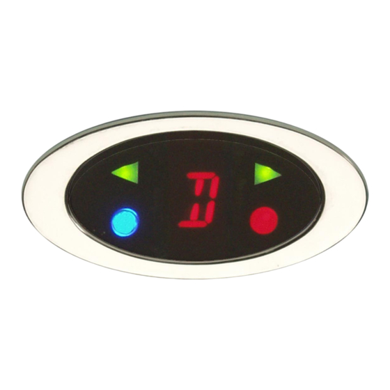
Operation:
The DGS-4 gear indicator unit works with Dakota Digital's gear position sending units (such as the GSS-
1000 or GSS-2000). The gear sending unit should be setup for one wire mode (see manual for gear sender).
The DGS unit will then display a letter or number indicating the current gear.
The DGS-4 also has 4 additional indicators. These are, left and right turn signal, high beam indicator, and a
miscellaneous warning light.
DGS-4
GEAR SHIFT INDICATOR
ORANGE (+) left turn indicator
BLUE (+) night dimming
PURPLE (+) high beam indicator
YELLOW 1 wire gear output from GSS-1000/2000
WHITE/BLACK (-) negative input for warning indicator *
BLACK ground for DGS-4
WHITE/RED (+) positive input for warning indicator *
RED fused +12V with key on
GREEN (+) right turn indicator
Dash Panel
DGS-4
C-clamp
nut
MOUNTING ILLUSTRATION
MAN# 650020a
Stud
Advertisement

Related Manuals for Dakota Digital DGS-4


Summary of Contents for Dakota Digital DGS-4
- Page 1 1000 or GSS-2000). The gear sending unit should be setup for one wire mode (see manual for gear sender). The DGS unit will then display a letter or number indicating the current gear. The DGS-4 also has 4 additional indicators. These are, left and right turn signal, high beam indicator, and a miscellaneous warning light.
- Page 2 Setup: Wire the DGS-4 according to the wiring diagram on the first page. The left turn, right turn and high beam indicators will light with a +12V signal on the wire. The warning indicator has two possible modes of operation, +12V activated and ground activated. Connect as follows depending on your application.
- Page 3 Figure 2 DGS-4 case dimensions in inches. TROUBLESHOOTING PROBLEM CAUSE SOLUTION Display reads -- Gear data (yellow wire) is Check wire for places it is shorted to ground or 12v or pinched or broken. Relocate broken. pinched wire and repair breaks or bare spots.
- Page 4 Any action for breach of any warranty hereunder, including any implied warranty of merchantability, must be brought within a period of 24 months from date of original purchase. No person or representative is authorized to assume, for Dakota Digital, any liability other than expressed herein in connection with the sale of this product.
Need help?
Do you have a question about the DGS-4 and is the answer not in the manual?
Questions and answers