Advertisement
Quick Links
JetNet 7310G Industrial 8 GbE plus 2 GbE SFP Ethernet Switch
Quick Installation Guide V1.0
The JetNet 7310G is an pure Gigabit Managed Switch with 8 ports Gigabit Ethernet plus IEEE
802.3at PoE/PSE function, and 2 Gigabit SFP for Gigabit Ethernet fiber connection.
The Switch system offers 240W system PoE Power budget with 35W forwarding capability in
each port with high voltage (54V) power input.
The Switch system's housing is designed with one pieces of heat-sink to dissipate heat when
perform high power PoE for DOM IP Camera, Wireless AP. It also provides excellent heat
dissipation, even working in road-side cabinet, it still can deliver high power to far-end
PoE-PDs. It also adopts comprehensive network feature with brilliant Electro-Magnetic
Susceptibility testing level carried out the ability for the Railway Track –Side surveillance.
Package Check List
JetNet 7310G
DIN Mounting kit
DB-9 to RJ-45 RS-232 Console Cable
Quick Installation Guide
Installation
Interface Introduction
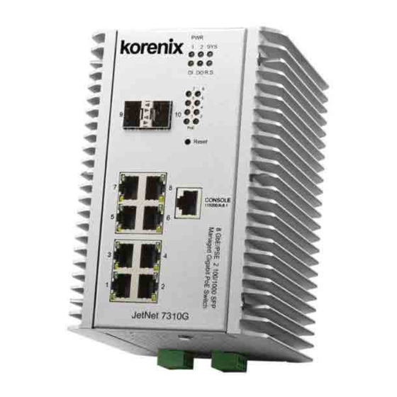
JetNet 7310G supports 8 ports Gigabit Ethernet RJ-45, and 2 ports Gigabit Ethernet SFP
socket for fiber connection.
PWR
1
2
SYS
DI
DO
R.S.
7
8
5
6
3
4
9
10
1
2
PoE
Reset
7
8
CONSOLE
115200.N.8.1
5
5
6
4
1
2
8 GbE/PSE 2 100/1000 SFP
Managed Gigabit PoE Switch
Mounting the unit
The DIN Rail clip on the rear of JetNet 7310G, and supports 35mm DIN rail.
Wiring the Power Inputs & Earth Grounding
1. Insert the positive and negative wires into the V+ and V- contact on the
terminal block connector.
2. Connect the Chassis
Grounding to Earth Ground
system to obtain electromagnetic
immunity to resist lighting,
electro static discharge and
electric fast transient.
3. Tighten the wire-clamp screws to prevent the power wires from being loosened.
Notes: The recommended working voltage is DC 53V. Use the UL Listed LPS Power supply
with output Rating 46~57 VDC, minimum 5A currents.
Wiring the Relay Output
The relay output contacts are in the bottom
side. The relay output (DO) is controlled by
the pre-defined operating rules.
To activate relay output function, please
refer to the User's Manual for more relay
output management information.
Notes: The relay contact only supports
0.5 A current, DC 24V. It is not recommended to apply voltage and current higher than the
specifications.
Wiring the Digital Input
The Digital Input (DI) contacts are in
the bottom. It accepts one external DC
type signal input and can be configured
to send alert message through Ethernet
when the signal is changed. The signal
may trigger and generated by external
power switch, like as door open trigger
switch for control cabinet.
Note: The DI accepts DC type signal and supports isolated input circuit with Digital High
Level input DC 11V~30V and Digital Low Level input DC 0V~10V. Do not apply voltage
higher than the specification; it may cause internal circuit damage or a wrong action of DI.
Connecting the Surge/Lighting protection
The surge protection activate screw located on the rear side that nearby the DIN rail clip.
Always tighten the screw and ensure the surge protection activate
screw is tighten with Earth-Ground well.
Note:
1. Ensure the Surge/Lighting is well connecting with
Chassis Grounding.
2. Remove the Surge/Lighting Screw before perform insulation/
Hi-pot testing.
3. Never install or work on/with the equipment or the cabling
during the period of its lightning activity.
Device Management
You can configure JetNet 7310G via the RS-232 console with the attached console cable. Or
you can remotely manage the switch via network. You can choose Telnet/SSH,
Web/HTTPS management.
Preparation for console management
Attach the RS-232 DB9 connector to your PC's COM port. Connect the RJ-45 connector to
the console port of the JetNet Switch.
1. Go to Start ► Program ► Accessories ► Communication ► Hyper Terminal
2. Give a name to the new console connection.
3. Choose the COM name and select the correct serial settings. The serial port settings are as
below: Baud Rate:115200/Parity: None/Data Bit: 8/Stop Bit: 1
4. After connected, you will see the Switch login request. Type the username and password
and then you can login. The default username is "admin", password is "admin".
5. Follow the manual to configure the software features.
Preparation for Web management
1. Launch the web browser on the PC.
2. Type http://JetNet Managed Switch_IP_Address (The default IP address is 192.168.10.1.),
then press Enter.
3. The login screen will appear next. Type in the user name and password and click "OK"
button. The default user name and password is admin/admin.
4. At the left column of the web management interface are the software features, where ring
column will list the available settings.
Support
5 Years Warranty
Each of Korenix's product is designed, produced, and tested with high industrial standard.
Korenix warrants that the product(s) shall be free from defects in materials and
workmanship for a period of five (5) years from the date of delivery provided that the
product was properly installed and used.
This warranty is voided if defects, malfunctions or failures of the warranted product are
caused by damage resulting from force measure (such as floods, fire, etc.), other external
forces such as power disturbances, over spec power input, or incorrect cabling; or the
warranted product is misused, abused, or operated, altered and repaired in an unauthorized
or improper way.
Attention! To avoid system damage caused by sparks, please DO NOT plug in power
connector when power is on.
The product is in compliance with Directive 2002/95/EC and 2011/65/EU of the
European Parliament and of the Council of 27 January 2003 on the restriction of the use of
certain hazardous substances in electrical and electronics equipment (RoHS Directives &
RoHS 2.0)
Korenix Customer Service
KorenixCARE is Korenix Technology's global service center, where our professional staffs
are ready to answer your questions at any time.
Email address of Korenix Global Service Center : KoreCARE@korenix.com
Advertisement

Subscribe to Our Youtube Channel
Related Manuals for Korenix JetNet 7310G


Summary of Contents for Korenix JetNet 7310G
- Page 1 Attach the RS-232 DB9 connector to your PC’s COM port. Connect the RJ-45 connector to immunity to resist lighting, The JetNet 7310G is an pure Gigabit Managed Switch with 8 ports Gigabit Ethernet plus IEEE the console port of the JetNet Switch.
- Page 2 接线的电源输入与地球接地 准备控制面板界面软件 概述 1.将正和负导线插入V +和V- 将RS-232 串口DB9连接到PC的串口。串口线的RJ-45连接器连接到JetNet交换机的 JetNet 7310G是具有8端口IEEE 802.3at PoE / PSE千兆以太网共电口以及2千兆SFP光 Console口。 接触端子台连接器上。 纤口的工业型网络管理交换机。交换机每个端口具有35W共电能力,系统提供240W 1. 计算机开始 程序集 附属应用程序 通讯 超级终端机界面 2. 连接机箱接地与系统大 PoE总共电功率。系统设计采用一体式散热模块为高阶DOM型网络监控摄像机,无 2. 建立一个超级终端机联机名称 地以便获得优良的电磁干 3.选择COM串口名称,并选择正确的串口设置。JetNet交换机的串口端口设置如 线AP存取时,进行高功率以太网供电时提供优异优异散热能力。 整体式散热结构设 扰保护,如静电,浪涌放电 下:115200bps, N, 8,1 ,快速脉冲放电。...
Need help?
Do you have a question about the JetNet 7310G and is the answer not in the manual?
Questions and answers