
Related Manuals for Korenix JetNet 7014G Series


Summary of Contents for Korenix JetNet 7014G Series
-
Page 1: User Manual
Korenix JetNet 7014G Series Industrial L3 Full Gigabit Managed Ethernet Switch User Manual Version1.0 Jun.,2017 www.korenix.com... - Page 2 Korenix JetNet 7014G Series Industrial L3 Full Gigabit Managed EthernetSwitch User’s Manual Copyright Notice Copyright 2006-2017 Korenix Technology Co., Ltd. All rights reserved. Reproduction in any form or by any means without permission is prohibited.
- Page 3 Federal Communications Commission (FCC) Statement This equipment has been tested and found to comply with the limits for a Class A digital device, pursuant to Part 15 of the FCC Rules. These limits are designed to provide reasonable protection against harmful interference when the equipment is operated in a commercial environment.
-
Page 4: Table Of Contents
2.14 Device Front Panel ..................147 2.15 Save ......................148 2.16 Logout ......................149 2.17 Reboot ......................149 3. Appendix ........................150 3.1 Product Specification ................... 150 3.2 Korenix Private MIB ..................154 3.3 About Korenix ....................154 3.4 Release History .................... 156... -
Page 5: Preparation For Management
1.1 Preparation for Serial Console In the unit package, Korenix attached one RJ-45 to RS-232 DB-9 console cable. Please attach RS-232 DB-9 connector to your PC’s COM port, connect RJ-45 connector to the Console port of the JetNet Managed Switch. If the serial cable is lost, please follow the serial console cable PIN assignment to find one.. -
Page 6: Preparation For Web Interface
Interface for web management 1.2.1 Web Interface Korenix web management page is developed by CGI (Common Gateway Interface). It allows you to use a standard web-browser such as Microsoft Internet Explorer,Mozilla, and Google Chrome to configure and interrogate the switch from anywhere on the network. - Page 7 1.2.2 Secured Web Interface Korenix web management page also provides secured management HTTPS login. All the configuration commands will be secured and will behard for the hackers to sniff the login password and configuration commands.
-
Page 8: Preparation For Telnet Console
The login screen will appear. Key in the user name and the password. The default user name and password is admin. Click on Enter or Login.Welcome page of the web-based management interface will then appear. Once you enter the web-based management interface, all the commands you see are the same as what you see by HTTP login. - Page 9 the “Telnet” protocol. 2. After click on Open, then you can see the cipher information in the popup screen. PressYes to accept the Security Alert. 3. After few seconds, the SSH connection to JetNet Managed Switchis opened. 4. Type the Login Name and its Password. The default Login Name and Password are admin / admin.You can see the screen as the below figure.
- Page 10 5. All the commands you see in SSH are the same as the CLI commands you see via RS232 console. The next chapter will introduce in detail how to use command line to configure the switch.
-
Page 11: Feature Configuration
IP address. Then you can remotely connect to its embedded HTML web pages or Telnet console. Korenix web management page is developed by CGI (Common Gateway Interface. It allows you to use a standard web-browser such as Microsoft Internet Explorer, or Mozilla, to configure and interrogate the switch from anywhere on the network. -
Page 12: Command Line Interface Introduction
2.1 Command Line Interface Introduction The Command Line Interface (CLI) is the user interface to the switch’s embedded software system. You can view the system information, show the status, configure the switch and receive a response back from the system by keying in a command. There are some different command modes. - Page 13 write Write running configuration to memory, network, or terminal Global Configuration Mode: Press configure terminal in privileged EXEC mode. You can thenenter global configuration mode. In global configuration mode, you can configure all the features that the system provides you. Type interface IFNAME/VLAN to enter interface configuration mode, exit to leave.
- Page 14 (Port) Interface Configuration: Press interface IFNAME in global configuration mode. You can thenenter interface configuration mode. In this mode, you can configure port settings. The port interface name for gigabit Ethernet port 1 is gi1..gigabit Ethernet port 10 is gi10. Type interface name accordingly when you want to enter certain interface configuration mode.
- Page 15 The command lists of the VLAN interface configuration mode. Switch(config)# interface vlan1 Switch(config-if)# description Interface specific description End current mode and change to enable mode exit Exit current mode and down to previous mode Interface Internet Protocol config commands ipv6 Interface Internet Protocol config commands list Print command list...
- Page 16 VLAN Interface In this mode, you can Enter: Type interface VLAN VID Switch(config-vlan)# Configuration configure settings for in global configuration mode. specific VLAN. Exit: Type exit or Ctrl+Z to global configuration mode. Type end to privileged EXEC mode. Here are some useful commands for you to see these available commands. Save your time in typing and avoid typing error.
-
Page 17: Basic Setting
2.2 Basic Setting The Basic Setting group provides you to configure switch information, IP address, User name/Password of the system. It also allows you to do firmware upgrade, backup and restore configuration, reload factory default, and reboot the system. Following commands are included in this group: 2.2.1 Switch Setting 2.2.2 Admin Password 2.2.3 IP Configuration... -
Page 18: Admin Password
are 64. System OID: The SNMP object ID of the switch. You can follow the path to find its private MIB in MIB browser. (Note: When you attempt to view private MIB, you should compile private MIB files into your MIB browser first.) System Description: The name of this managed product. - Page 19 Confirm Password: You need to type the new password again to confirm it. Once you finish configuring the settings, click on Apply to apply your configuration. RADIUS Server/ Secondary RADIUS Server RADIUS Server: The IP address of Radius server Shared Key: It is the password for communicate between switch and Radius Server. Server Port: UDP port of Radius server.
- Page 20 IPv6 Configuration –An IPv6 address is represented as eight groups of four hexadecimal digits, each group representing 16 bits (two octets). The groups are separated by colons (:), and the length of IPv6 address is 128bits. An example of an IPv6 address is: 2001:0db8:85a3:0000:0000:8a2e:0370:7334. The Leading zeroes in a group may be omitted.
-
Page 21: Time Setting
IPv6Neighbor Table: shows the IPv6 address of neighbor, connected interface, MAC address of remote IPv6 device, and current state of neighbor device. The system will update IPv6 Neighbor Table automatically, and user also can click the icon “Reload” to refresh the table. 2.2.4 Time Setting Time Setting source allow user to set the time manually or through NTP server. - Page 22 05 (GMT-08:00) Pacific Time (US & Canada) , Tijuana 06 (GMT-07:00) Arizona 07 (GMT-07:00) Mountain Time (US & Canada) 08 (GMT-06:00) Central America 09 (GMT-06:00) Central Time (US & Canada) 10 (GMT-06:00) Mexico City 11 (GMT-06:00) Saskatchewan 12 (GMT-05:00) Bogota, Lima, Quito 13 (GMT-05:00) Eastern Time (US &...
- Page 23 54 (GMT+07:00) Bangkok, Hanoi, Jakarta 55 (GMT+07:00) Krasnoyarsk 56 (GMT+08:00) Beijing, Chongqing, Hong Kong, Urumqi 57 (GMT+08:00) Irkutsk, Ulaan Bataar 58 (GMT+08:00) Kuala Lumpur, Singapore 59 (GMT+08:00) Perth 60 (GMT+08:00) Taipei 61 (GMT+09:00) Osaka, Sapporo, Tokyo 62 (GMT+09:00) Seoul 63 (GMT+09:00) Yakutsk 64 (GMT+09:30) Adelaide 65 (GMT+09:30) Darwin 66 (GMT+10:00) Brisbane...
-
Page 24: Jumbo Frame
After time synchronized, the system time will display the correct time of the PTP server. Mode: Auto mode: the switch performs PTP Master and slave mode. Master mode: switch performs PTP Master only. Slave mode: switch performs PTP slave only. Synchronization Interval: Select items: -3(128ms) -2(256ms) -1(512ms) 0(1s) 1(2s) 2(4s) 3(8s) 4(16s) Announce Interval:... -
Page 25: Dhcp Server
Once you finish your configuration, click on Apply to apply your configuration. 2.2.6 DHCP Server You can select to Enable or Disable DHCP Server function. The Managed Switch will assign a new IP address to link partners. - Page 26 DHCP Server configuration After selecting to enable DHCP Server function, type in the Network IP address for the DHCP server IP pool, Subnet Mask, Default Gateway address and Lease Time for client. Once you have finished the configuration, click Apply to activate the new configuration Global Setting: You can enable or disable the local DHCP server Address Pool Add: Add a address pool setting into local DHCP server.
- Page 27 This section allows you to exclude IP addresses within the network range from being assigned to devices. Excluded IP: An IP address you want to exclude from being leased.The Excluded Address List table contains the following fields: Index: The indexes of the excluded IP addresses. IP Address: The excluded IP addresses.
- Page 28 You can type in the specified IP addressand MAC address, and then click Add to add a new MAC&IP address binding rule for a specified link partner, like PLC or any device without DHCP client function. To remove from the binding list, just select the rule to remove and click Remove.
- Page 29 You canEnable or Disable the DHCP Relay Agent function. Click the Apply button to apply the DHCP Relay Agent settings. Helper Address: Type the IP address of the target DHCP Server. There are 4 available IP addressesthat can be configured. Click Add to add the IP address and Remove to delete it.
-
Page 30: Backup And Restore
Click the Apply button to apply the Circuit ID setting for a port after selecting a port and the associated setting. Port: This is the logical port of the switch. Default (VLAN/Port): This is the default value of the Circuit ID. User Defined: This is a user defined value of the Circuit ID. -
Page 31: Firmware Upgrade
Click Submit to load or save the configuration. 2.2.8 Firmware Upgrade You can update the latest firmware for your device. Korenix provides the latest firmware on Korenix Web site. Updated firmware may include new features, bug fixes, or other software... -
Page 32: Load Default
changes, please check the release notes for the information. We suggest you use the latest firmware before installing the switch to the customer site. Local File This section allows you to upload a firmware image that is stored locally on your computer. Select File: Select a firmware image from your computer. -
Page 33: Cli Commands For Basic Setting
Command Line Switch Setting Switch(config)# hostname System Name WORD Network name of this system Switch(config)# hostname JN7014G Switch(config)# Switch(config)# snmp-server location Taipei System Location Switch(config)# snmp-server contact korecare@korenix.com System Contact Switch# show snmp-server name Display Switch Switch# show snmp-server location Taipei... - Page 34 Manufacturing Date : 2017/06/06 Software Information : Loader Version : 1.0.0.2 Firmware Version : 1.0-20170606-17:43:32 System OID : 1.3.6.1.4.1.24062.2.3.12 Copyright 2006-2015 Korenix Technology Co., Ltd. Switch# show hardware led led information mac mac address Switch# show hardware mac MAC Address : 00:12:77:FF:01:B0...
- Page 35 Description : N/A Administrative Status : Enable Operating Status : Up DHCP Client : Disable Primary IP Address : 192.168.10.8/24 IPv6 Address : fe80::212:77ff:feff:6666/64 Switch# show running-config ……… interface vlan1 ip address 192.168.10.8/24 no shutdown ip route 0.0.0.0/0 192.168.10.254/24 Switch(config)# interface vlan1 IPv6 Address/Prefix Switch(config-if)# ipv6 address 2001:0db8:85a3::8a2e:0370:7334/64...
- Page 36 Primary peer : N/A Secondary peer : N/A Switch# show clock Sun Jan 1 04:14:19 2006 (GMT) Greenwich Mean Time: Dublin, Edinburgh, Lisbon, London Switch# show clock timezone clock timezone (26) (GMT) Greenwich Mean Time: Dublin, Edinburgh, Lisbon, London Switch# show ptpd PTPd is enabled Mode: Slave JumboFrame...
- Page 37 Switch(config-dhcp)# ip dhcp excluded-address DHCP Server – A.B.C.D IP address Excluded Address Switch(config-dhcp)# ip dhcp excluded-address 192.168.10.123 <cr> Switch(config-dhcp)# ip dhcp static DHCP Server – MACADDR MAC address Static IP and MAC Switch(config-dhcp)# ip dhcp static 0012.7700.0001 A.B.C.D leased IP address binding Switch(config-dhcp)# ip dhcp static 0012.7700.0001 192.168.10.99...
- Page 38 192.168.10.123 Manual Binding List IP Address MAC Address --------------- -------------- 0012.7701.0203 Leased Address List IP Address MAC Address Leased Time Remains --------------- -------------- -------------------- Switch# show ip dhcp relay DHCP Relay DHCP Relay Agent ON Information IP helper-address : 192.168.10.200 Re-forwarding policy: Replace Backup and Restore Switch# copy startup-config tftp: 192.168.10.33/default.conf...
-
Page 39: Port Configuration
2.3 Port Configuration Port Configuration group enables you to enable/disable port state, orconfigure port auto- negotiation, speed, and duplex, flow control, rate limit control and port aggregation settings.It also allows you to view port status and aggregation information. Following commands are included in this group: 2.3.1 Understand the port mapping 2.3.2 Port Control 2.3.3 Port Status... - Page 40 Select the port you want to configure and make changes to the port. State: You can enable or disable the state of this port. Once you click Disable, the port stops to link to the other end and stops to forward any traffic. The default setting is Enable which means all the ports are workable.
-
Page 41: Port Status
you made will be lost when the switch is powered off. 2.3.3 Port Status The Port Status page displays the current port status, including Small Form Factory (SFP) fiber transceiver with Digital Diagnostic Monitoring (DDM) function that provides real time information of SFP transceiver and allows you to diagnostic the optical fiber signal received and launched. -
Page 42: Rate Control
If the plugged DDM SFP transceiver is not certified by Korenix, the DDM function is not supported, but the communication is not disabled. 2.3.4 Rate Control Rate limiting is used to control the rate of traffic that is sent or received on a network interface. -
Page 43: Storm Control
The ports support port ingress and egress rate control. Ingress Rule(Kbps): The rate range of Ingress rate is from 70 Kbps to 256000 Kbps and zero means no limit. The default value is 8 Mbps. Egress Rule(Kbps): The rate range of Egress rate is from 70 Kbps to 256000 Kbps and zero means no limit. -
Page 44: Port Trunking
The aggregated ports can interconnect to the other switch which also supports Port Trunking. Korenix Supports 2 types of port trunking. One is Static Trunk, the other is 802.3ad. When the other end uses 802.3ad LACP, you should assign 802.3ad LACP to the trunk. - Page 45 Group ID: Group ID is the ID for the port trunking group. Ports with same group ID are in the same group. Trunk Type: Static and 802.3ad LACP. Each Trunk Group can only support Static or 802.3ad LACP. When the other end uses 802.3ad LACP, you should assign 802.3ad LACP to the trunk. When the other end uses non-802.3ad, you can then use Static Trunk.
-
Page 46: Command Lines For Port Configuration
Group ID: Display the Trunk Group ID in Aggregation Setting. Type: Static or LACP set up in Aggregation Setting. Aggregated: When LACP links well, you can see the member ports in aggregated column. Individual: When LACP is enabled, member ports of LACP group which are not connected to correct LACP member ports will be displayed in the Individual column. - Page 47 Control Flowcontrol on for port 1 set ok! Switch(config-if)# flowcontrol off Flowcontrol off for port 1 set ok! Port Status Switch# show interface gi1 Port Status Interface gigabitethernet1 Description : N/A Administrative Status : Enable Operating Status : Connected Duplex : Full Speed : 100 MTU: 1518 Flow Control :off...
- Page 48 SWITCH# show storm-control Display – Rate Storm-control for Port 1 Configuration and Broadcast packets : Disabled Rate : 1000 (packets/s) port status Destination Lookup Failure packets : Enabled Rate : 1000 (packets/s) Multicast packets : Disabled Rate : 1000 (packets/s) Storm-control for Port 2 Broadcast packets : Disabled Rate : N/A...
- Page 49 internal LACP internal information neighbor LACP neighbor information port-setting LACP setting for physical interfaces system-id LACP system identification system-priority LACP system priority SWITCH# show lacp port-setting LACP Port Setting : Port Priority Timeout ----- --------- -------- 32768 Long 32768 Long 32768 Long ……….
-
Page 50: Power Over Ethernet (Jetnet Poe Switch Only)
2.4 Power over Ethernet (JetNet PoE Switch only) Power over Ethernet is the key features of JetNet PoE Switch. It is fully compliance with IEEE 802.3af and IEEE 802.3at that include 1-event with IEEE 802.1AB LLDP classification and 2-event classification. 2.4.1 PoE Control Warning Water Level: If the power utilization is more than the Power Budget level, the system sends a warning event. - Page 51 Detection)that help user to mainten the PD’s status and save the maintenance time and human resource.Thisfuction is patented by Korenix. Once enable this function, the PoE Switch will request PD system in the period of time (cycle time). If PD system does not echo the request, the switch will turn-off PoE power and then turn-on PoE power again.
-
Page 52: Poe Schedule
2.4.2 PoE Schedule The PoE Schedule supports hourly and weekly base PoE schedule configuration. Select Enableor Disable on the target port and select the checkbox on the target time. ClickApply to apply the settings. Click Cancel to clear the settings. Click Reloadto reload the information. -
Page 53: Poe Status
2.4.3 PoE Status The PoE Status page shows the system PoE status and the operating status of each PoE Port. Total Power Budget: This is the maximum PoE output power (in watts). Total Output Power: Total output power of PoE system (in watts). Warning Water Level: If power utilization is more than the warning level, the system sends a warning event. -
Page 54: Network Redundancy
This is Korenix Patterned MultiRing Technology. The Ring ports can be LACP/Port Trunking ports, after aggregated ports to a group, the group of ports can act as the Ring port of the Ring. This is Korenix Pattened TrunkRing Technology. - Page 55 configuration. Spanning Tree Protocol (STP; IEEE 802.1D) provides a loop-free topology for any LAN or bridged network. STP Mode: Select the spanning tree protocol: STP, RSTP or MSTP or Disable Bridge Address: The MAC addres used to identify the bridge. This value cannot be modified.
-
Page 56: Stp Port Configuration
Since different RSTP aware switches may have their own mechanism to calculate the message age. So that this is most possibly occurred when interoperate different vendors’ RSTP aware switches together. The maximum volume of the Korenix RSTP domain is 23, configure the MAX Age lower than 23 is recommended. - Page 57 Select the port you want to configure and you will be able to view current settings and status of the port. Path Cost: Enter a number between 1 and 200,000,000. This value represents the “cost” of the path to the other bridge from the transmitting bridge at the specified port. Port Priority: Enter a value between 0 and 240, using multiples of 16.
-
Page 58: Mstp Configuration
Root Information You can see Root Address, Root Priority, Root Port, Root Path Cost and the Max Age, Hello Time and Forward Delay of BPDU sent from the root switch. Port Information You can see port Role, Port State, Path Cost, Port Priority, Link Type, Edge Port mode and Aggregated (ID/Type). - Page 59 A Common Spanning Tree (CST) interconnects all adjuacent MST regions and acts as a virtual bridge node for communications with STP or RSTP nodes in the global network. MSTP connects all bridges and LAN segments with a single Common and Internal Spanning Tree (CIST).
- Page 60 MSTP Region Configuration This page allows configure the Region Name and its Revision, mapping the VLAN to Instance and check current MST Instance configuration. The network can be divided virtually to different Regions. The switches within the Region should have the same Region and Revision leve.
-
Page 61: Mstp Port Configuration
Instance Priority: A value used to identify the MST instance. The MST instance with the lowest value has the highest priority and is selected as the root. Enter a number 0 through 61440 in increments of 4096. Click on Add to apply your settings. MST Instance Configuration This page allows you to see the current MST Instance Configuration you added. -
Page 62: Mstp Information
Link Type: There are 3 types for you select. Auto, P2P and Share. Some of the rapid state transitions that are possible within RSTP depend upon whether the port of concern can only be connected to another bridge (i.e. it is served by a point-to- point LAN segment), or if it can be connected to two or more bridges (i.e. - Page 63 Multiple Super Ring (MSR) technology is Korenix’s 3 generation Ring redundancy technology. This is patented and protected by Korenix and is used in countries all over the world. MSR ranks the fastest restore and failover time in the world, 0 ms for restore and about milliseconds level for failover for 100Base-TX copper port.
- Page 64 RingID. Version: The version of Ring can be changed here. There are three modes to choose: Rapid Super Ring as default; Super ring for compatible with Korenix 1 general ring and Any Ring for compatible with other version of rings.
- Page 65 Path Cost is the same, the port with larger port number will become the blocking port. Rapid Dual Homing: Rapid Dual Homing is an important feature of Korenix 3 generation Ring redundancy technology. When you want to connect multiple RSR or form redundant topology with other vendors,RDH could allow you to have maximum 7 multiple links for redundancy without any problem.
- Page 66 Rapid Dual Homing Port Configuration Ring ID: The Ring Identifier referring to this Ring. Auto Detect: Enable RDH auto detect RDH port mode. Port: Enable RDH on specific ports. Click “Apply” to apply the setting. Click “Cancel” to clear the modification. 2.5.8 MSR Information Ring ID: The Ring Identifier referring to this Ring (Chain).
-
Page 67: Erps Configuration
2.5.9 ERPS Configuration Ethernet Ring Protection Switching (ERPS) is an Ethernet ring protocol defined in ITU-T G.8032. ERPS is capable of recovering from a network failure under 50ms and prevents loops from existing within the ring. The page allows you to configure the switch to be a member of an ERPS ring ERPS: Enable or Disable ERPS on the switch. - Page 68 2.5.10 Command Lines Feature Command Line Global Enable Switch(config)# spanning-tree enable Disable Switch(config)# spanning-tree disable Mode (Choose the Switch(config)# spanning-tree mode Spanning Tree mode) rst the rapid spanning-tree protocol (802.1w) stp the spanning-tree protocol (802.1d) mst the multiple spanning-tree protocol (802.1s) Bridge Priority Switch(config)# spanning-tree priority <0-61440>...
- Page 69 Switch(config-mst)# instance 1 vlan VLANMAP target vlan number(ex.10) or range(ex.1-10) Switch(config-mst)# instance 1 vlan 2 Display Current MST Switch(config-mst)# show current Configuration Current MST configuration Name 65[korenix] Revision 65535 Instance Vlans Mapped -------- -------------------------------------- 1,4-4094 Config HMAC-MD5 Digest: 0xB41829F9030A054FB74EF7A8587FF58D ------------------------------------------------...
- Page 70 3(-> The instance is not applied after Abort settings-- Config HMAC-MD5 Digest: 0xB41829F9030A054FB74EF7A8587FF58D ------------------------------------------------ RSTP The mode should be rst, the timings can be configured in global settings listed in above. Global Information Active Information Switch# show spanning-tree active Spanning-Tree : Enabled Protocol : MSTP Root Address : 0012.77ee.eeee Priority : 32768...
- Page 71 Name 67korenix Revision 65535 Instance Vlans Mapped -------- -------------------------------------- 1,4-4094 Config HMAC-MD5 Digest: 0xB41829F9030A054FB74EF7A8587FF58D ------------------------------------------------ Display all MST Switch# show spanning-tree mst Information ###### MST00 vlans mapped: 1,4-4094 Bridge address 0012.77ee.eeee priority 32768 (sysid 0) Root this switch for CST and IST Configured max-age 2, hello-time 15, forward-delay 20, max- hops 20...
- Page 72 Link Type : Auto (Point-to-point) BPDU Guard : Disabled Boundary : Internal(MSTP) BPDUs : sent 6352, received 0 Instance Role State Cost Prio.Nbr Vlans mapped -------- ---------- ---------- -------- ---------- --------------------- Designated Forwarding 200000 128.1 1,4-4094 Designated Forwarding 200000 128.1 Designated Forwarding 200000 128.1...
- Page 73 <0-7> extension ID 0-7 (default is 0) default Note: auto-detect is recommended for dual Homing.. Super Chain Switch(config-multiple-super-ring)# super-chain disable Switch(config-multiple-super-ring)# super-chain border Switch(config-multiple-super-ring)# super-chain member Switch(config-multiple-super-ring)# super-chain edge-port PLIST Port Ring Info Ring Info Switch# show multiple-super-ring [Ring ID] [Ring1] Ring1 Current Status : Disabled Role...
- Page 74 R-APS(NR) : sent 0, received 0 Node State Transition count 0 Switch# ConfigureERPS Switch(config)# erps enable Start the Multiple Super Ring for the switch disable Stop the Multiple Super Ring for the switch version the protocol version node-role The node role of ERPS node ring-port The ring port1 and port2 of the ERPS The ring Ring Protection Link of the ERPS...
-
Page 75: Vlan
2.6 VLAN A Virtual LAN (VLAN) is a “logical” grouping of nodes for the purpose of limiting a broadcast domain to specific members of a group without physically grouping the members together. That means, VLAN allows you to isolate network traffic so that only members of VLAN could receive traffic from the same VLAN members. -
Page 76: Vlan Configuration
2.6.1 VLAN Configuration Use this page to assign the Management VLAN, create the static VLAN, and assign the Egress rule for the member ports of the VLAN. The management VLAN ID is the VLAN ID of the CPU interface so that only member ports of the management VLAN can ping and access the switch. -
Page 77: Vlan Port Configuration
Click Remove Selected to remove the selected static VLAN. Click Reload to reload static VLAN configuration. Note: Always remember to go toSave page to save the settings. Otherwise, the settings you made will be lost when the switch is powered off. 2.6.2 VLAN Port Configuration Tag-based VLANs are based on the IEEE 802.1Q specification. -
Page 78: Vlan Information
port should be Untag, it indicates that the egress packet is always untagged. This is configured in the Static VLAN Configuration table. • 802.1Q Tunnel Uplink - QinQ is applied to the ports which connect to the S-VLAN. The port receives a tagged frame from the S-VLAN. When the packets are forwarded to the S-VLAN, the S-VLAN tag is kept. -
Page 79: Pvlan Configuration
2.6.4 PVLAN Configuration The private VLAN helps to resolve the primary VLAN ID shortage, client ports, isolation and network security issues. The Private VLAN provides primary and secondary VLAN within a single switch. Note: You must have previously configured a VLAN in the VLAN Configuration screen. VLAN ID: •... - Page 80 2.6.5 PVLAN Port Configuration The PVLAN Port Configuration page allows you to configure the port configuration and private VLAN associations. Port Configuration PVLAN Port Type: Normal: Normal ports remain in their original VLAN configuration. Host: Host ports can be mapped to the secondary VLAN. Promiscuous: Promiscuous ports can be associated to the primary VLAN.
-
Page 81: Gvrp Configuration
2.6.6 PVLAN Information The PVLAN Information page allows you to see the private VLAN information. Click Reload to refresh the page contents. 2.6.7 GVRP Configuration GARP VLAN Registration Protocol (GVRP) allows you to set-up VLANs automatically rather than manual configuration on every port on every switch in the network. GVRP conforms to the IEEE 802.1Q specification.This defines a method of tagging frames with VLAN configuration data that allows network devices to dynamically exchange VLAN configuration information with other devices. - Page 82 GVRP Protocol: Enable/Disable GVRP globally. State: After enabling GVRP globally, you can still Enable/Disable GVRP by port. Join Timer: Controls the interval of sending the GVRP Join BPDU (Bridge Protocol Data Unit). An instance of this timer is required on a per-port, per-GARP participant basis. Leave Timer: Control the time to release the GVRP reservation after received the GVRP Leave BPDU.
- Page 83 802.1Q Tunnel = Switch(config-if)# switchport dot1q-tunnel mode access access Set the interface as an access port of IEEE 802.1Q tunnel mode 802.1Q Tunnel Uplink = uplink Set the interface as an uplink port of IEEE uplink 802.1Q tunnel mode Port Accept Frame Switch(config)# inter gi1 Type Switch(config-if)# acceptable frame type all...
- Page 84 Show Running Building configuration... Current configuration: hostname Switch vlan learning independent ……… ……… interface gigabitethernet5 switchport access vlan add 1-2,10 switchport dot1q-tunnel mode access interface gigabitethernet6 switchport access vlan add 1-2 switchport trunk allowed vlan add 10 switchport dot1q-tunnel mode uplink VLAN Configuration Create VLAN (2) Switch(config)# vlan 2...
- Page 85 Ports ---- ------------ ------- -------------------------- ----------------- --------- VLAN1 Static gi1-7,gi8-10 VLAN2 Unused test Static gi4-7,gi8-10 gi1- 3,gi7,gi8-10 Display – VLAN Switch# show interface vlan1 Interface vlan1 interface information Description : N/A Administrative Status : Enable Operating Status : Up DHCP Client : Disable Primary IP Address : 192.168.10.1/24 IPv6 Address : fe80::212:77ff:feff:2222/64 GVRP configuration...
-
Page 86: Traffic Prioritization
2.7 Traffic Prioritization Quality of Service (QoS) provides traffic prioritization mechanism which allows users to deliver better service to certain flows. QoS can also help to alleviate congestion problems and ensure high-priority traffic is delivered first. This section allows you to configure Traffic Prioritization settings for each port with regard to setting priorities. - Page 87 In JetNet, users can freely assign the mapping table or follow the suggestion of the 802.1p standard. Korenix uses 802.p suggestion as default values. You can find CoS values 1 and 2 are mapped to physical Queue 0, the lowest queue. CoS values 0 and 3 are mapped to physical Queue 1, the low/normal physical queue.
- Page 88 Click Apply to apply the setting. Click Cancel to clear the modification. 2.7.3 DSCP-Priority Mapping This page is to change DSCP values to Priority mapping table. The system provides 0~63 DSCP priority level. Each level can map to one priority ID After configuration, press Apply to enable the settings.
-
Page 89: Cli Commands Of The Traffic Prioritization
2.7.4 CLI Commands of the Traffic Prioritization Command Lines of the Traffic Prioritization configuration Feature Command Line QoS Setting Queue Scheduling – Switch(config)# qos queue-sched Strict Priority Round Robin sp Strict Priority wrr Weighted Round Robin Switch(config)# qos queue-sched sp The queue scheduling scheme is setting to Strict Priority. - Page 90 ……….. CoS-Queue Mapping Format Switch(config)# qos cos-map PRIORITY Assign an priority (7 highest) Switch(config)# qos cos-map 1 QUEUE Assign an queue (0-7) Note: Format: qos cos-map priority_value queue_value Map CoS 0 to Queue 1 Switch(config)# qos cos-map 0 1 The CoS to queue mapping is set ok. Map CoS 1 to Queue 0 Switch(config)# qos cos-map 1 0 The CoS to queue mapping is set ok.
-
Page 91: Multicast Filtering
d2| 0 1 2 3 4 5 6 7 8 9 -----+---------------------- 0 | 1 0 0 0 0 0 0 0 1 1 1 | 1 1 1 1 1 1 2 2 2 2 2 | 2 2 2 2 3 3 3 3 3 3 3 | 3 3 4 4 4 4 4 4 4 4 4 | 5 5 5 5 5 5 5 5 6 6 5 | 6 6 6 6 6 6 7 7 7 7... - Page 92 2.8.1 IGMP Query Enable/Disable: SelectEnale or Disable. Version: V1 means IGMP V1 General Query and V2 means IGMP V2 General Query. The query will be forwarded to all multicast groups in the VLAN. Query Interval(s): The period of query (seconds) sent by querier. Enter a number between 1and 65,535.
- Page 93 IGMP Snooping Global Setting Select Enable/Disable IGMP Snooping. After enabling IGMP Snooping, you can then enable IGMP Snooping for specific VLAN using the IGMP Snooping VLAN Setting table. IGMP Snooping VLAN Setting VLAN: Refers to the VLAN number that was configured using the VLAN Configuration page.
-
Page 94: Gmrp Configuration
you made will be lost when the switch is powered off. IGMP Snooping Table This table shows the IGMP groups the switch is aware of. Multicast Address: The multicast group's IP address. VLAN ID: The VLAN ID the multicast group is a member of. Interface: The port the multicast group is a member of. - Page 95 2.8.4 CLI Commands of the Multicast Filtering Command Lines of the multicast filtering configuration Feature Command Line IGMP Snooping IGMP Snooping - Switch(config)# ip igmp snooping Global IGMP snooping is enabled globally. Please specify on which vlans IGMP snooping enables Switch(config)# ip igmp snooping<?>...
- Page 96 Switch(config-if)# ip igmp version 2 Disable Switch(config)# int vlan 1 Switch(config-if)# no ip igmp Display Switch# sh ip igmp interface vlan1 enabled: Yes version: IGMPv2 query-interval: 125s query-max-response-time: 10s Switch# show running-config …. interface vlan1 ip address 192.168.10.17/24 ip igmp no shutdown …….
-
Page 97: Routing (Layer3 Managed Switch Only)
2.9 Routing (Layer3 Managed Switch only) Layer 3 Routing Feature is the most important feature of the the Layer 3Managed Ethernet Switch. Since the hosts located in different broadcast domain can’t communicate by themselves, once there is a need to communicate among the different VLANs, the layer 3 routing feature is requested. - Page 98 value in the real world. Type the new time and press “Apply” to change it. Total Entry Count: This count represents for the count of total entries the ARP Table has. Static Entry Count: This count represents for the count the static entries user configured. Dynamic Entry Count: This count represents for the count the ARP table dynamically learnt.
- Page 99 IP Interface Configuration This page allows you Enable the IP Routing interface and assign the IP Address for it. Before creating IP Interface, you should create VLAN Interface and assign the member port to the VLAN. Please refer to the VLAN Configuration for detail. The IP Interface table listed all the created VLAN automatically, you can change the setting for each VLAN here.
- Page 100 2.9.3 Router This page allows you configure the Route Entry and check the Routing table. 2.9.3.1 Static Route Entry Configuration Default Route The default route allows the stub network to reach all unknown networks through the route. The stub area has only one way and one route to other networks. Within the stub area, there are multiple networks and run their own routing protocols, however, while the want communicate with unknown network, the traffic will be forwarded to the default route.
- Page 101 Static Route Table This table displays the routing table information Destination: The destination address of static route entry. Netmask: The destination address netmask of static route entry. Gateway: The gateway IP address of static route entry. Distance: The distance of static route entry. Metric: The metric of static route entry.
- Page 102 When a router receives a neighbor’s table, it examines it entry by entry. If the destination is new, it is added to the local routing table. If the destination is known before and the update provides a smaller metric, the existing entry in the local routing table is replaced. Adds 1 (or sometimes more if the corresponding link is slow) to the metric.
- Page 103 RIP Protocol: Choose the RIP Version 1 or Version 2 or Disable RIP protocol in here. Click the Apply button to apply RIP protocol setting. Routing for Networks: All the networks no matter directly connected or learnt from other router/switch should be added to the switch. The format is IP Network/bit mask. For example, 192.168.100.0/24.
- Page 104 The figure asbelow is the example OSPF network. There are 6 routing switch, A~F. The Routers/Switch periodically sends “Hello” packets to the neighbors and exchange OSPF link state with each other and then update the Routing table of each router/switch. Use the communication between A to C for example.
- Page 105 OSPF Protocol: Enable or Disable the OSFP routing protocol. Router ID: The router ID can be any IP address, however, the IP address of the existed local interface is suggested. With such IP address, you can find the router/switch easier. Router ID is used while connected multiple OSPF routers/switches to the same broadcast domain, the lowest Router ID will be selected as the Designated Router in the network.
- Page 106 Metric Type: OSPF exterior metric type of the redistribute type: none, 1 or 2. Click the Remove Selected button to remove the selected redistribute type. Click the Reload button to reload this page. 2.9.5.2 OSPF Interface Configuration This page allows user to see the OSPF network address and the parameters of each interface.
- Page 107 The JetNet Switch is usually installed as internal router of a single Area environment. While there are multiple areas in the network, this page allows modify the Area information and Virtual Link. Area: This field indicates the area ID. Select the ID you want to modify here. Default Cost: The default cost of the area ID.
- Page 108 Virtual Link (A.B.C.D.): You can configure the virtual link. One area must be common area between two endpoint routers to create virtual links. Click the Add button to add a virtual link for the selected area. Click the Remove Selected button to remove selected virtual link of selected area. 2.9.5.4 OSPF Neighbor Table This page allows user to see the OSPF Neighbor information.
-
Page 109: Vrrp Configuration
Attempt - no recent information has been received from the neighbor but a more concerted effort should be made to contact the neighbor. Init - an Hello packet has recently been seen from the neighbor, but bi-directional communication has not yet been established. 2 way - communication between the two routers is bi-directional. - Page 110 2.9.6.1 VRRP Configuration The fields allow you to create the Virtual Router Interface. All the layer 3 switches within the same VRRP domain should be located within the same IP network and equips with the same Virtual ID and Virtual IP address. Interface: Select the interface for the VRRP domain.
- Page 111 While the Preempt is Disable and the interface is VRRP Master, there is no change while the link is recovered. The VRRP backup acts as the Master before restart the switches. Click “Apply Selected” to change the setting. “Remove” to remove the entry. “Reload” to reload the new entry and settings.
- Page 112 2.9.7 CLI Commands of the Routing Feature Command Lines of the Routing configuration Feature Command Line Age Time Switch(config)# arp aging-time <10-21600> seconds (10-21600) Switch(config)# arp aging-time 1200 (20min for example) Static ARP Entry Switch(config)# arp A.B.C.D IP address of ARP entry aging-time Aging Time Switch(config)# arp 192.168.100.1 MACADDR 48-bit hardware address of ARP entry...
- Page 113 Change Interface to Switch(config-if)# shutdown DOWN <cr> Switch(config-if)# shutdown Interface vlan1 Change to DOWN Activate the IP Switch(config-if)# no shutdown Interface arping for the MAC arp: SIOCDARP(pub): No such file or directory ARPING to 192.168.10.254 from 192.168.10.43 via vlan1 Sent 3 probe(s) (3 broadcast(s)) Received 0 reply (0 request(s), 0 broadcast(s)) Interface vlan1 Change to UP Show ip routing status...
- Page 114 192.168.2.0/24 [110/40] via 192.168.5.254, vlan5, 00:09:31 C>* 192.168.2.0/24 is directly connected, vlan2 O>* 192.168.3.0/24 [110/30] via 192.168.5.254, vlan5, 00:09:31 O>* 192.168.4.0/24 [110/20] via 192.168.5.254, vlan5, 00:09:31 192.168.5.0/24 [110/10] is directly connected, vlan5, 00:09:31 C>* 192.168.5.0/24 is directly connected, vlan5 192.168.10.0/24 [110/10] is directly connected, vlan1, 00:07:15 C>* 192.168.10.0/24 is directly connected, vlan1 O>* 192.168.12.0/24 [110/40] via 192.168.5.254, vlan5,...
- Page 115 RIP Split Horizon Switch(config-router)# passive-interface IFNAME Interface name default default for all interfaces Switch(config-router)# passive-interface default <cr> RIP default Metric Switch(config-router)# default-metric (usually = 1) <1-16> Default metric RIP Setting Switch# show ip rip status Routing Protocol is "rip" Sending updates every 30 seconds with +/-50%, next due in 23 seconds Timeout after 180 seconds, garbage collect after 120 seconds...
- Page 116 according to bandwidth compatible OSPF compatibility list default-information Control distribution of default information default-metric Set metric of redistributed routes distance Define an administrative distance distribute-list Filter networks in routing updates End current mode and change to enable mode exit Exit current mode and down to previous mode list Print command list...
- Page 117 Number of LSA 5 IP OSPF Datasheet Switch# show ip ospf database OSPF Router with ID (192.168.3.254) Router Link States (Area 0.0.0.0) Link ID ADV Router Age Seq# CkSum Link count 192.168.3.253 192.168.3.253 928 0x80000009 0xf3b2 2 192.168.3.254 192.168.3.254 927 0x8000000a 0xd4aa 192.168.5.254 192.168.5.254 230 0x80000006 0xc248 Net Link States (Area 0.0.0.0)
- Page 118 network 192.168.3.0/24 area 0.0.0.0 network 192.168.11.0/24 area 0.0.0.0 ip routing …….. Multicast Routing (Before enable MRoute, the IP Interfaces’ setting should be configured and activated first.) Enable the MRoute & witch(config)# ip multicast 224.0.1.10 vlan 1 interface gi2-3 Configure the static vlan specify the ingress VLAN entry interface specify an interface list to add to...
-
Page 119: Snmp
2.10 SNMP Simple Network Management Protocol (SNMP) is a protocol used for exchanging management information between network devices. SNMP is a member of the TCP/IP protocol suite. An SNMP managed network consists of two main components: agents and a manager. An agent is a management software module that resides in a managed switch. -
Page 120: Snmp V3 Profile
and Private as their default community name,this might be the leakage of the network security. 2.10.2 SNMP V3 Profile SNMP v3 can provide more security functions when the user performs remote management through SNMP protocol. It delivers SNMP information to the administrator with user authentication;... -
Page 121: Snmp Traps
This page allows users to Enable SNMP Trap, configure the SNMP Trap server IP, Community name, and trap Version V1 or V2. After configuration, you can see the change of the SNMP pre-defined standard traps and Korenix pre-defined traps. The pre- defined traps can be found in Korenix private MIB. - Page 122 Click the Apply button to apply trap configurations. SNMP Trap Server Server IP: SNMP Trap Server IP address. Community: SNMP Trap Server community string. Version: SNMP Trap version, V1 or V2c Click the Add button to add a SNMP Server. Trap Server Profile This table displays SNMP Trap server information.
-
Page 123: Security
2.11 Security JetNet Managed Switchprovides several security features for you to secure your connection. The Filter Set is also known as Access Control List. The ACL feature includestraditional Port Security and IP Security. 2.11.1 Filters (Access Control List) The Filter Set is known as Access Control List feature. There are 2 major types, one is MAC Filter, it is also known as Port Security in other JetNet series. - Page 124 2000 – 2699: IP Extended Access List (expanded range) After entering the IP Filter Group number, click the Add to create the new Filter Group. Group Number: Number of the Filter Group. Source IP: This is the source IP address of the packet. Source Wildcard: This is the mask of the IP address.
- Page 125 Action: This is the filter action, which is to deny or permit the packet. Click the Delete button to remove the Filter you selected. 2.11.1.2 MAC Filter (Port Security) Packet filtering can help limit network traffic and restrict network use by certain users or devices.
- Page 126 MAC Filter Setting You can configure the MAC Filter. Group Name: This is the name of the MACFilter Group. Source MAC: This is the source MAC Address of the packet. Source Wildcard: This is the mask of the MAC Address. Destination MAC: This is the destination MAC Address of the packet.
- Page 127 2.11.1.3 Filter Attach This page allows you to attach filters created on the IP Filter and MAC Filter pages to ports on the switch. Filter Attach Port: The port you want to attach a filter to. MAC Filter: Select a MAC address based filter to attach to the interface. Select "--" to remove an attached MAC address filter.
- Page 128 2.11.2 IEEE 802.1x 2.11.2.1 802.1XConfiguration IEEE 802.1X is the protocol that performing authentication to obtain access to IEEE 802 LANs. It is port-base network access control. With the function, JetNet Switch could control which connection is available or not. System AuthControl: Select Enable or Disable the 802.1x authentication. Authentication Method: RADIUS is an authentication server that provide key for authentication, with this method, user must connect switch to server.
- Page 129 primary radius server down. Click Apply to apply the settings. Note: Always remember to go to Save page to save the settings. Otherwise, the settings you made will be lost when the switch is powered off. Local RADIUS User User Name: The user name of the local RADIUS user. Password: The password of the local RADIUS user.
- Page 130 Port control: Force Authorized means this port is authorized; the data is free to in/out. Force Unauthorized means the port is blocked. If users want to control this port with Radius Server, please select Auto for port control. Reauthentication: Enable this field, switch will ask client to re-authenticate. The default time interval is 3600 seconds.
- Page 131 Re-Auth Period(s): control the Re-authentication time interval, 1~65535 is available. Quiet Period(s): When authentication failed, Switch will wait for a period and try to communicate with radius server again. Tx period(s): the time interval of authentication request. Supplicant Timeout(s): the timeout for the client authenticating Sever Timeout(s): The timeout for server response for authenticating.
- Page 132 Port: The port identifier. Port Control: Force Authorized means that this port is Authorized and the data is free to travel in and out. Force unauthorized is just the opposite and the port is blocked. Authorized Status: The authorize status of the port. Authorized Supplicant: The MAC address of the authorized supplicant.
- Page 133 deny Specify packets to reject permit Specify packets to forward End current mode and down to previous mode exit Exit current mode and down to previous mode list Print command list Negate a command or set its defaults quit Exit current mode and down to previous mode remark Access list entry comment Example 1: Edit MAC Switch(config-ext-macl)#permit...
- Page 134 Display Switch# show mac-address-table static Destination Address Address Type Vlan Destination Port ------------------- --------------- ------- ------------------------ 0012.7701.0101 Static 802.1x (shot of dot1x) enable Switch(config)# dot1x system-auth-control Switch(config)# diable Switch(config)# no dot1x system-auth-control Switch(config)# authentic-method Switch(config)# dot1x authentic-method local Use the local username database for authentication radius Use the Remote Authentication Dial-In User Service (RADIUS) servers for authentication...
- Page 135 interface Interface name radius Remote Access Dial-In User Service statistics Interface name username User Name in local radius database Switch# show dot1x<cr> = Switch# show dot1x all You can check all dot1x information for all interfaces. Click Ctrl + C to exit the display Switch# show dot1x interface fa1 Supplicant MAC ADDR <NONE>...
-
Page 136: Warning
2.12 Warning JetNet Switch provides several types of Warning features for you to remote monitor the status of end devices or the change of your network. The features include Fault Relay, System Log and SMTP E-mail Alert. 2.12.1 Fault Relay The JetNe Switch provides alarm relay output (DO) that can support multiple fault conditions. -
Page 137: Event Selection
DI State: Activates the relay based on the state of the digital input. If DI State is set to Low the relay will activate when the digital input is off. If DI State is set to High the relay will activate when the digital input is on. -
Page 138: Syslog Configuration
rebooted. Authentication Failure: When selected the switch generates a notification if somebody attempts to log into the switch with incorrect credentials. Time Synchronize Failure: When selected the switch generates a notification if it fails to synchronize with an NTP server. This event is only applicable if the switch is configured to synchronize with an NTP server. -
Page 139: Smtp Configuration
Syslog Mode: There are two System Log modes provided by JetNet Switch, local mode and remote mode. Local Mode - In this mode, JetNet Switch will print the occurred events selected in the Event Selection page to System Log table of JetNet Switch. You can monitor the system logs in Monitor and Diag / Event Log page. -
Page 140: Cli Commands
Email Alert: Select Enable / Disable to the email alert feature. SMTP Server IP: Enter the IP address of the email Server. Mail Account: Enter the Email account for SMTP server. Authentication: Check to enable the authentication feature SMTP server. User Name: Enter the Email account name for SMTP server. - Page 141 ring ring failure Dry Output Switch(config)# relay 1 dry <0-65535> turn on period in second Switch(config)# relay 1 dry 5 <0-65535> turn off period in second Switch(config)# relay 1 dry 5 5 Ping Failure Switch(config)# relay 1 ping 192.168.10.33 <cr> reset reset a device Switch(config)# relay 1 ping 192.168.10.33 reset <1-65535>...
- Page 142 Switch(config)# smtp-server server 192.168.10.100 ACCOUNT SMTP server mail account, ex: admin@korenix.com Switch(config)# smtp-server server 192.168.10.100 admin@korenix.com SMTP Email Alert set Server: 192.168.10.100, Account: admin@korenix.com ok. admin@example. Receiver mail Switch(config)# smtp-server receipt admin@example. SMTP Email Alert set receipt 1: com ok.
-
Page 143: Monitor And Diag
2.13 Monitor and Diag JetNet Switch provides several types of features for you to monitor the status of the switch or diagnostic for you to check the problem when encountering problems related to the switch. The features include MAC Address Table, Port Statistics, Port Mirror, Event Log and Ping. -
Page 144: Mac Address Table
2.13.2 MAC Address Table In this page, you can change the Aging time, add Static Unicast MAC Address, monitor the MAC address or sort them by different packet types and ports. MAC Address Table In this MAC Address Table, you can see all the MAC Addresses learnt by the switch fabric. - Page 145 Type: Indicates the port type. Link: Indicates the link status, Connected or Disconnected. State: Indicates the link state, Enable or Disable. RX Good: The count of good frames received, which is the total number of received unicast, broadcast, multicast and pause frames. RX Bad: The count of bad frames received, which is the total number of undersize, fragment, oversize, jabber, RXErr and FCSErr frames.
-
Page 146: Port Mirroring
2.13.4 Port Mirroring Port mirroring (also called port spanning) is a tool that allows you to mirror the traffic from one or more ports onto another port, without disrupting the flow of traffic on the original port. Any traffic that goes into or out of the Source Port(s) will be duplicated at the Destination Port. -
Page 147: Event Logs
2.13.5 Event Logs The System Log feature was introduced in 4.12.3SysLog Configuration . When System Log Local mode is selected, JetNet Switch will record occurred events in local log table. This page shows this log table. The entry includes the index, occurred data and time and content of the events. -
Page 148: Cli Commands Of The Monitor And Diag
2.13.7 CLI Commands of the Monitor and Diag Command Lines of the Monitor and Diag configuration Feature Command Line MAC Address Table Ageing Time Switch(config)# mac-address-table aging-time 350 mac-address-table aging-time set ok! Note: 350 is the new ageing timeout value. Add Static Unicast Switch(config)# mac-address-table static 0012.7701.0101 MAC address... - Page 149 Show Aging timeout Switch# show mac-address-table aging-time time the mac-address-table aging-time is 300 sec. Port Statistics Port Statistics Switch# show rmon statistics gi4 (select interface) Interface gigabitethernet4 is enable connected, which has Inbound: Good Octets: 178792, Bad Octets: 0 Unicast: 598, Broadcast: 1764, Multicast: 160 Pause: 0, Undersize: 0, Fragments: 0 Oversize: 0, Jabbers: 0, Disacrds: 0 Filtered: 0, RxError: 0, FCSError: 0...
- Page 150 Switch(config)# lldp timer <5-254> Valid range is 5~254 Ping Ping IP Switch# ping 192.168.10.33 PING 192.168.10.33 (192.168.10.33): 56 data bytes 64 bytes from 192.168.10.33: icmp_seq=0 ttl=128 time=0.0 ms 64 bytes from 192.168.10.33: icmp_seq=1 ttl=128 time=0.0 ms 64 bytes from 192.168.10.33: icmp_seq=2 ttl=128 time=0.0 ms 64 bytes from 192.168.10.33: icmp_seq=3 ttl=128 time=0.0 ms 64 bytes from 192.168.10.33: icmp_seq=4 ttl=128 time=0.0 ms --- 192.168.10.33 ping statistics ---...
-
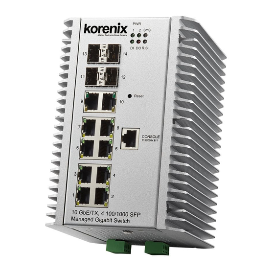
Page 151: Device Front Panel
2.14 Device Front Panel The Device Front Panel allows you to see the LED status of the switch For Example, JetNet 7310G front panel status is shown as below Click on Reload to reload the status. Note: No CLI command for this feature... -
Page 152: Save
2.15 Save The Save Configuration page saves any changes to the configuration to the flash.If the switch loses power before clicking save configuration causes loss of the new settings. Applying changes on web user interface pages do not save the changes to the flash. Click Save to Flash to save your new configuration. -
Page 153: Logout
2.16 Logout The Logout command allows you to manually logout the web connection. The web connection will be logged out automatically if you don’t input any command after 30 seconds. Click Yes to logout Command Lines: Feature Command Line SWITCH> exit Logout SWITCH# exit 2.17 Reboot... -
Page 154: Appendix
3. Appendix 3.1 Product Specification Technology Standard IEEE 802.3 10 Base-T Ethernet IEEE 802.3u 100 Base-TX Fast Ethernet IEEE 802.3ab 1000 Base-T IEEE 802.3x Flow Control and Back-pressure IEEE 802.1AB Link Layer Discovery Protocol (LLDP) IEEE 802.1p Class of Service (CoS) IEEE 802.1Q VLAN and GVRP IEEE 802.1D-2004 Rapid Spanning Tree Protocol (RSTP) IEEE 802.1s Multiple Spanning Tree Protocol (MSTP) - Page 155 Windows based NMS (Network Management System) –Korenix NMS and Korenix View for device discovery and topology map auto construct Network Time Protocol NTP with daylight saving and localize time sync function Management IP Predefined Host IP address for management host login security...
- Page 156 Cyber Network Redundancy New generation Korenix Ring Redundancy Technology, Includes Rapid Multiple Super Ring Super Ring, Rapid Dual Homing, TrunkRing , MultiRing , Super (MSR Chain Rapid Dual Homing Multiple uplink paths to one or multiple upper Switch, up to 256 Groups...
- Page 157 1000Mbps Gigabit Ethernet SFP port (#11~#14): SFP Socket with 1000Mbps Fiber Transceiver Auto Detection, and with Digital Diagnostic Monitoring (DDM) for optical fiber quality inspection Power input: 4-Pin Removable Terminal Block Connector Digital Input, Output: 4-Pin Removable Terminal Block Connector RS-232 Console: RJ-45, Baud Rate:115200bps, N,8,1 Digital Input: Semi Digital Input (Low: 0~10V, High:11~30V) Digital Output: Dry Relay Output with Normal Open operating mode with...
-
Page 158: Korenix Private Mib
Less Time At Work! Fewer Budget on applications! The Korenix business idea is to let you spend less time at work and fewer budget on your applications. Do you really want to go through all the troubles but still end up with low quality products and lousy services? Definitely not! This is why you need Korenix. - Page 159 5 Years Warranty Each of Korenix’s product line is designed, produced, and tested with high industrial standard. Korenix warrants that the Product(s) shall be free from defects in materials and workmanship for a period of five (5) years from the date of delivery provided that the Product was properly installed and used.
-
Page 160: Release History
Korenix Technologies Co., Ltd. Business service: sales@korenix.com Customer service: koreCARE@korenix.com 3.4 Release History Edition Date Modifications V1.0 2017/06/28 First Release...
Need help?
Do you have a question about the JetNet 7014G Series and is the answer not in the manual?
Questions and answers