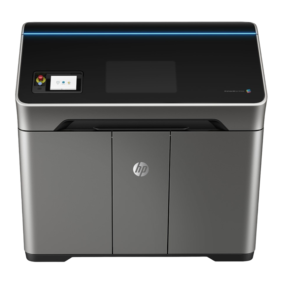
HP Jet Fusion 340 Product Documentation Site Preparation Manual

Hide thumbs Also See for Jet Fusion 340:

Advertisement

Quick Links

HP Jet Fusion 340 3D Printer
HP Jet Fusion 540 3D Printer
HP Jet Fusion 580 Color 3D Printer
Product Documentation
Site Preparation Guide

Advertisement

Table of Contents
loading

Summary of Contents for HP Jet Fusion 340

  • Page 1 HP Jet Fusion 340 3D Printer HP Jet Fusion 540 3D Printer HP Jet Fusion 580 Color 3D Printer Product Documentation Site Preparation Guide...
  • Page 2 Intel® and Intel Core™ are trademarks of Intel Edition 7 change without notice. Corporation in the U.S. and other countries. The only warranties for HP products and Microsoft® and Windows® are U.S. registered services are set forth in the express warranty trademarks of Microsoft Corporation.
  • Page 3: Table Of Contents

    Electrical requirements ................................. 12 5 Plan your computer and network environment ..........................26 Important considerations ..............................26 Introduction to the HP Cloud environment ........................28 Information about networking and security ........................30 Networking requirements ..............................31 Computer requirements ................................ 31 Test your connection to HP Cloud ............................
  • Page 4 7 Fill out and return the site preparation checklist ..........................41 Site preparation guide checklist ............................42 Appendix A Before and after installation ............................... 46 Acclimate the printer before installation ..........................46 Acclimate the agent cartridges and printheads ........................ 46 Recycle the consumables ..............................
  • Page 5: Introduction

    At the end of this document is a checklist, which you should fill out, sign, and return to the reseller or HP sales representative. What to expect...
  • Page 6 User guide ● Legal information ● Limited warranty ● Cloud connection security information ● Chapter 1 Introduction ENWW...
  • Page 7: Plan For The Printer Delivery Truck

    Plan for the printer delivery truck Read this section to obtain the information you need to make a successful coordinated delivery. Special site access requirements If your location will require security clearance for the printer delivery truck, you will need to work with the trucking company to arrange security clearance before delivery is attempted.
  • Page 8: Plan For Moving And Uncrating The Printer

    You may decide to hire a specialist mover, who should be familiar with your site and should read the moving ● information in this guide. Ensure that you have the equipment needed to handle the crate: HP recommends a fork lift or pallet jack. ● CAUTION: After the printer has been uncrated, do not attempt to move it with a fork lift or pallet jack, which would damage the printer.
  • Page 9: Moving The Crated Printer

    Moving the crated printer Determine whether the printer crate can be moved to the final location (see Printer crate dimensions and weight on page 3). Check whether the dimensions of the doorways and hallways along the delivery path meet minimum clearance requirements listed below.
  • Page 10: Plan The Printer Production Area And Environment

    HP recommends that the recommended operation space be maintained. Additionally, the printer should be protected against risks potentially created by other nearby installed equipment. That is, the printer can be installed in the same room as other equipment, but it should be installed away from other equipment that could potentially create a hazard during operation.
  • Page 11: Printer Space Requirements

    After printing the parts and removing the material in the processing station, you must clean the parts to remove the thin layer of material attached to the surface. To do this, you need a bead-blasting machine. HP recommends a bead-blasting machine with the following specifications: Manual or automatic operation ●...
  • Page 12: Moving The Uncrated Printer

    CAUTION: Unloading and moving the printer and all system components is your responsibility and not HP's. Failure to provide the required moving and lifting equipment could result in personal injury or printer damage during installation.
  • Page 13: Floor Characteristics

    IMPORTANT: Hold the printer using the handles, and always move the printer with the top lid closed if possible. If the lid must remain open in order to move the printer through a narrow door, do not pull or push the printer directly using the open lid, as this may cause the hinges to deform, and the top lid may become misaligned.
  • Page 14 Environmental requirements (continued) Specification Comments Storage and reshipping temperature −25 to +55°C (−13 to +131°F) Storage humidity < 90% RH without condensation Ventilation options Room size Minimum air exchanges Lamp exhaust Exhaust hood Option 1 Small 5 ACH Direct duct (paasive or active) Option 2 Small 10 ACH...
  • Page 15 HP Jet Fusion Muffler accessory (5RD52A) The muffler accessory is recommended for installations in which the printer exhaust is vented into the room. Diverts hot air exhaust away from operators and adjacent surfaces ● Easy connection and disconnection with a simple hose clamp (included) ●...
  • Page 16: Electrical Requirements

    Electrical requirements NOTE: Electrical requirements are not the same as for other HP Jet Fusion 3D printers; please review the requirements carefully. A certified electrician is required for the setup and configuration of the building’s electrical system as well as connecting the power cable to the printer according to the electrical installation details in this guide.
  • Page 17 HP does not recommend a specific UPS for your printer. Should you decide to use a UPS in line with the input of the printer, the UPS must be rated to meet the power requirements of the printer. It should be connected by a certified electrician in accordance with the Electrical Code requirements of the local jurisdiction where the equipment is installed.
  • Page 18 Power wires can be L1 & L2 or L & N, depending on the country. This product has been evaluated to ±10% of the rated nominal voltage range (200–240 V) to allow for line fluctuation. If the wire is more than 4.5 m (15 ft) long, HP recommends increasing the wire gauge appropriately. WARNING! Ensure that mains fault current is compatible with proper operation of the protection devices incorporated in the equipment (5 kA rated interrupting capacity).
  • Page 19 Power wires can be L1 & L2 or L & N, depending on the country. This product has been evaluated to ±10% of the rated nominal voltage range (200–240 V) to allow for line fluctuation. If the wire is more than 4.5 m (15 ft) long, HP recommends increasing the wire gauge appropriately. WARNING! Ensure that mains fault current is compatible with proper operation of the protection devices incorporated in the equipment (5 kA rated interrupting capacity).
  • Page 20 If the Electrical Code requirements of the local jurisdiction require an external RCCB or GFCI for earth fault protection, install a device with sensitivity of 100 mA or higher, with appropriate rated current for the supply configuration. Also ensure that other protective devices for earth fault protection upstream from the printer are always greater than the one selected for the printer.
  • Page 21 Remove seven T20 screws from the printer chassis if present. Locate the box containing the KIT PWR Cord Single WW Blind Plate, HP PN M2K85-61695. Item Part number Quantity Description M2K85-01339 Cover breaker power box blank 0360-3729 Terminal jumper 0515-5471 SCREW-MACH M4 X 0.7 8MM-LG PH CS ROHS...
  • Page 22 203 mm (8 in) from the grommet or strain relief. Apply a ferrule to the PE wire; the electrician must provide the correct ferrule. Install two jumpers HP PN 0360-3729 in the terminal blocks as shown in the picture, and tighten four flat- head screws.
  • Page 23 Example of a single-circuit connection to the building’s electrical system on page 15 if needed. Install the plate and secure it with seven T20 M4 screws from the KIT PWR Cord Single WW Blind Plate kit. Tighten seven screws. ENWW Electrical requirements...
  • Page 24 The four power wires are circuit 1: L1N1 and circuit 2: L2N2. This product has been evaluated to ±10% of the rated nominal voltage range (200–240 V) to allow for line fluctuation. If the wire is more than 4.5 m (15 ft) long, HP recommends increasing the wire gauge appropriately. WARNING! Ensure that mains fault current is compatible with proper operation of the protection devices incorporated in the equipment (5 kA rated interrupting capacity).
  • Page 25 The four power wires are circuit 1: L1N1 and circuit 2: L2N2. This product has been evaluated to ±10% of the rated nominal voltage range (200–240 V) to allow for line fluctuation. If the wire is more than 4.5 m (15 ft) long, HP recommends increasing the wire gauge appropriately. WARNING! Ensure that mains fault current is compatible with proper operation of the protection devices incorporated in the equipment (5 kA rated interrupting capacity).
  • Page 26 Power line disturbances Reliable operation of your printer depends on the availability of relatively noise-free AC power. In order to ensure optimum performance and reliability, your printer should be protected from variations in ● line voltage, which are common to production printing environments. Lighting, line faults, or the power switching commonly found in machinery in factory environments can generate line transients that far exceed the peak value of the applied voltage.
  • Page 27 Remove seven T20 screws from the printer chassis, if present. Locate the box containing the KIT PWR Cord Single WW Blind Plate, HP PN M2K85-61695. Item Part number Quantity Description M2K85-01339 Cover breaker power box blank 0360-3729 Terminal jumper (DO NOT INSTALL FOR TWO-CIRCUIT CONFIGURATION) 0515-5471 SCREW-MACH M4 X 0.7 8MM-LG PH CS ROHS...
  • Page 28 Attach the power cable to the plate, install a strain relief to the plate, and make sure the protective earth conductor extends a minimum of 203 mm (8 in) from the grommet or strain relief. Apply a ferrule to the protective earth wire; the electrician must provide the correct ferrule. Connect the four wires to the terminal block as shown below, and connect the protective earth wire to the protective earth terminal block.
  • Page 29 Install the plate and secure it with seven T20 M4 screws from the KIT PWR Cord Single WW Blind Plate kit. Tighten the seven screws. ENWW Electrical requirements...
  • Page 30: Plan Your Computer And Network Environment

    If you already own an HP 3D printer, your computers, HP 3D Center account, and network may be ready, but HP recommends reading this chapter anyway. You must also make sure you are running the latest version of HP SmartStream 3D Command Center in all your machines.
  • Page 31 Customer Machine Data does not include design files, parts files, job contents, or part geometries. By default, job name is not sent but you can opt in for it to be used in the HP 3D Center apps (when available).
  • Page 32: Introduction To The Hp Cloud Environment

    HP SmartStream 3D Command Center Server needs to be installed in only one computer that is permanently running (it never goes to sleep or standby mode) and has access to the HP Cloud and all the printers. It needs to be always on to monitor devices and transfer their information to the cloud.
  • Page 33 Introduction to HP 3D Center by PrintOS In order to complete your site preparation and the installation of your HP 3D devices, you will need to become familiar with HP 3D Center by PrintOS; and create, at least, an organization and a user account associated with it.
  • Page 34: Information About Networking And Security

    How to get access to HP 3D Center You will need to create your organization and first user. If your HP representative has not provided you with an invitation to create them, you can do it manually by navigating to http://www.hp3dcenter.com...
  • Page 35: Networking Requirements

    The Command Center Server computer needs to allow incoming traffic to the Command Center Server ● application so that Command Center Clients can connect to the server. To give Command Center Server access to the HP Cloud, you should check that your network is not blocking ● the following endpoints: www.printos.com, port 443 (or https://www.printos.com)
  • Page 36: Test Your Connection To Hp Cloud

    IMPORTANT: Running Build Manager in a virtual environment is not supported. If you are planning to run non-HP software, make sure your computer complies with its requirements and that it is installed before the agreed date of printer installation. Test your connection to HP Cloud You are responsible for testing your network before the day of installation to check your connection to the HP Cloud from the computer running Command Center Server.
  • Page 37 Ensure that this computer will run 24/7 by disabling all policies that could lead the computer to switch to sleep or standby mode. Install the HP SmartStream 3D Command Center Server into the computer you have selected to be the server of the system, meeting the requirements explained in...
  • Page 38 Server. The IP address and the port number are also displayed in the tray icon. IMPORTANT: HP strongly recommends configuring a hostname or static IP address rather than a DHCP address for the Server computer, to allow Clients to find the Server reliably. IP addresses can change in DHCP environments.
  • Page 39 Use your HP 3D Center by PrintOS credentials to sign in, as already explained, from the icon at the top right of the screen. When you have signed in, the red ball beside the icon disappears. If you click the icon again, the panel shows user information.
  • Page 40 Stay connected to the Server to save your configuration. Click Advanced. Enable the option Use a proxy server. Fill in the hostname and port of your proxy. If necessary, add the username and password. Click Save to finish the configuration and send it to the Command Center Server. Chapter 5 Plan your computer and network environment ENWW...
  • Page 41: Final Checks

    Final checks Check the connection to HP 3D Center To ensure that your site is ready, you need to verify that a HP 3D Command Center device has been added to your HP 3D Center account: Connect to http://www.hp3dcenter.com/...
  • Page 42 In the left-hand menu, click the icon. In the list of your devices, you should see a new HP 3D Command Center device. Chapter 5 Plan your computer and network environment ENWW...
  • Page 43: Plan For Printer Installation In The Production Area

    Plan for printer installation in the production area Software installation HP software available for your system can be found here: http://www.hp.com/go/jetfusion340/software/, http://www.hp.com/go/jetfusion540/software/ or http://www.hp.com/go/jetfusion580color/software/. Required supplies and equipment You are responsible for providing the following items, which should be ready on the day of installation.
  • Page 44 Glass beads of diameter 210–297 μm (50–70 mesh) – HP’s recommended bead blasting system requires a compressed air source of 13–16 CFM to operate at the ● recommended air pressure of 2.8 bar (40 psi). See the documentation of your bead blasting system for compressed air requirements.
  • Page 45: Fill Out And Return The Site Preparation Checklist

    The customer must complete all three sections on this page. Once you have completed the checklist, sign it and send it to your reseller or HP sales representative a minimum of two weeks before the delivery date. The customer information, delivery/installation address, and installation contacts sections must be filled out and returned with a signed checklist before printer delivery can be scheduled.
  • Page 46: Site Preparation Guide Checklist

    ‘Not true’ to one of the statements. If your answer takes you to a STOP, work out the situation until the requirement is met, or contact your HP authorized reseller to work out a solution. Step...
  • Page 47 Go to the next step. The people who will operate the printer have HP highly recommends training users of the printer appropriate training to be aware of the hazards to and other post-processing equipment about the...
  • Page 48 HP Support Engineer to finish the network setup, with HP 3D Center and connected to the HP Cloud connect to the HP Cloud, and register with HP 3D on the day of the installation.
  • Page 49 Date of site preparation completion (mm/dd/yyyy) Customer name Customer signature Date ENWW Site preparation guide checklist...
  • Page 50: Appendix A Before And After Installation

    Recycle the consumables HP provides many free and convenient ways to recycle your used HP lamps, cartridges, and other consumables; see https://hp.com/recycle/. Where this program is not available, dispose of the consumables according to local regulations.
  • Page 51: Waste Disposal

    Dispose of all waste according to local regulations. Material storage, handling, and disposal should be performed according to local laws. See the Safety Data Sheets http://www.hp.com/go/msds for adequate handling and storage. Follow your Environmental Health and Safety processes and procedures.
  • Page 52: Appendix B Ducts And Hvac Recommendation

    Ducts and HVAC recommendation Energy balance Air conditioning in the work area should take into account that the equipment produces heat. The temperature of the air coming out of the printer may be up to 90°C (194°F) at the lamp exhaust duct, at sea level. Typically, the printer's power dissipation without local exhaust is in the range of 4–6 kW (13.6–20.5 kBTU/h).
  • Page 53: Small Room Layout Example

    You should provide a minimum of 6 ACH (air changes per hour) of fresh air ventilation and a minimum room ● volume of 35 m³ (1236 ft³). HP recommends 10 ACH for optimum operator comfort mainly if the room is smaller than 35 m³ (1236 ft³).
  • Page 54 Lamp duct recommendation In order for the printer to function correctly, the lamp exhaust duct should create no more than 125 Pascals of back-pressure at 3680 liters per minute (0.5 inches of water at 130 ft³/min) of air flow. In order to achieve this with a passive exhaust duct: A duct of at least 10 cm (4 in) is required ●...
  • Page 55: Option 2: No Direct Connection From The Lamp

    If the above recommendations cannot be met, a powered exhaust duct may be used: Powered exhaust systems should provide 3680 liters per minute (130 ft³/min) of flow. ● Powered lamp exhaust ducts connected to the lamp outlet must provide an air gap of at least 10 cm (4 in) ●...
  • Page 56 An optional muffler accessory may be added to reduce noise from the lamp exhaust. Contact your sales ● representative for more information. Appendix B Ducts and HVAC recommendation ENWW...
  • Page 57: Option 3: Large Room Or Multiple-Printer Configuration

    However, some facilities may require that printers be installed into larger spaces, or that multiple printers be installed in a shared space. Although 10 air changes per hour are still recommended, HP understands that this may not be feasible in spaces larger than 90 m³.

This manual is also suitable for:

Jet fusion 540Jet fusion 580

Table of Contents