Table of Contents
Advertisement
Quick Links
Advertisement
Table of Contents

Related Manuals for THORLABS ERM200


Summary of Contents for THORLABS ERM200
- Page 1 ERM200, ERM210, ERM220 Extinction Ratio Meter User Guide 2023...
- Page 2 Version: Date: 24-Jul-2023 Copyright © 2023 Thorlabs...
-
Page 3: Table Of Contents
ERM2xx Series Extinction Ratio Meter Table of Contents Chapter 1 Safety Chapter 2 Intended Use Chapter 3 Introduction Ordering Codes and Accessories Chapter 4 Getting Started Parts List Operating Instructions Chapter 5 Operating Elements Setup Adapter Mounting Direct Operation 5.4.1 ER Measurement View 5.4.2 Power View... - Page 4 ERM2xx Series Extinction Ratio Meter Chapter 10 Manufacturer Address Chapter 11 Copyright and Exclusion of Liability Chapter 12 Thorlabs Worldwide Contacts...
-
Page 5: Safety
This precision device is only serviceable if returned and properly packed into the complete original packaging including the cardboard inserts. If necessary, ask for replacement packaging. Refer servicing to qualified personnel! Changes to this device cannot be made nor may components not supplied by Thorlabs be used without written consent from Thorlabs. Attention... -
Page 6: Intended Use
The ERM200, ERM210, and ERM220 devices are used in photonics re- search and development applications. The ERM200, ERM210, and ERM220 devices are designed for laboratory use only. These devices may not be used or integrated into equipment that is applied in pharmaceutical, medical or military applica- tions. -
Page 7: Introduction
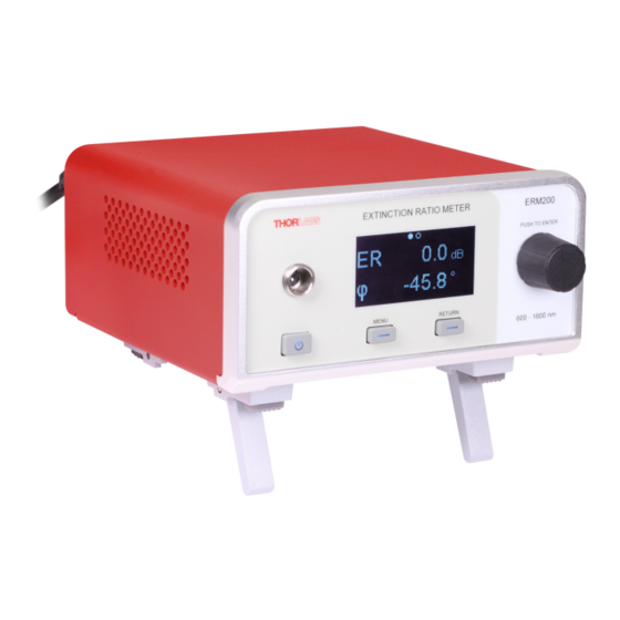
PM fibers or pigtailing of laser diodes with PM fibers. The ERM2xx series models cover different wavelength ranges from 400 nm up to 2500 nm. The ERM200 module is optimized for 600 nm to 1600 nm, the ERM210 module for 400 nm to 700 nm, and the ERM220 module for 1200 nm to 2500 nm. -
Page 8: Getting Started
Fiber Connector Adapters To accommodate for the use of the ERM2xx modules with different PM fiber connectors, Thorlabs of- fers 6 different adapters for the connectors noted in parentheses: ERM2F (Wide-Key FC/PC), ERM2F2 (Narrow-Key FC/PC), ERM2A (Wide-Key FC/APC), ERM2A2 (Narrow-Key FC/APC), ERM2L (LC/PC), and ERM2S (SC/PC). -
Page 9: Operating Elements
2. Connect the ERM2xx module to the power network using the supplied power cord. 3. Identify the fiber adapter for the ERM2xx module which matches the connector on the fiber un- der investigation. The available Thorlabs fiber adapters for the ERM2xx series are listed in the chapter Ordering Codes and Accessories. -
Page 10: Adapter Mounting
SC/PC Mounting steps 1. Push the adapter with the side labeled "Thorlabs" onto the fiber adapter connection port. 2. Screw the locking ring on the adapter to the port to secure the connection. 3. Mount the fiber connector to the adapter on the ERM2xx device. -
Page 11: Er Measurement View
Then press RETURN. The minimum ER value measured at that moment is then displayed in the ERmin display. 3. ERmax shows the maximum extinction ratio in dB since the last ERmax-monitor reset was per- formed. It also shows the corresponding misalignment angle in degrees: Rev: 1.0, 24-Jul-2023 © 2023 Thorlabs Page 7... -
Page 12: Power View
ERM2xx Series Extinction Ratio Meter Chapter 5 Operating Instructions To get to the ERmax mode, go to the Settings View and select ER_max from the mode parameter as described above. To redetermine the maximum extinction ratio, press the MENU button after selecting the ERmax mode: Then press RETURN. -
Page 13: Monitor Out Port
The monitor output port (BNC) provides the measured PER as voltage signal between 0 V to 5 V (High-Z, Conversion Factor 0.1 V/dB). This is convenient for active alignment of PM fibers. The BNC Monitor Out connector is compatible with Thorlabs Vytran®... -
Page 14: 32-Bit Operating System
ERM2xx Series Extinction Ratio Meter Chapter 5 Operating Instructions In this section the location of drivers and files required for programming in different environments are given for installation under Windows 8.1, Windows 10 (32 and 64 bit) and Windows 11 (32 and 64-bit). Note The ERM2-Series driver contains 32-bit and 64-bit versions. - Page 15 Sample\sample.prj Source file: C:\Program Files\IVI Foundation\VISA\WinNT\TLERM200\Examples\CVI C Sample\sample.c Example for C# Solution file: C:\Program Files\IVI Foundation\visa\WinNT\TLERM200\Examples\MS VS 2012 CSharp Demo\Thorlabs.ERM200.CSharp_Sample.sln Project file: C:\Program Files\IVI Foundation\visa\WinNT\TLERM200\Examples\MS VS 2012 CSharp Demo\Thorlabs.ERM200.CSharp_Sample.csproj Example for LabVIEW™ C:\Program Files\National Instruments\LabVIEW xxxx\In- str.lib\TLERM200\TLERM200.llb Rev: 1.0, 24-Jul-2023 ©...
-
Page 16: 64-Bit Operating System
ERM2xx Series Extinction Ratio Meter Chapter 5 Operating Instructions (LabVIEW™ container file with driver vi's and an example. "LabVIEW xxxx" stands for actual LabVIEW™ installation folder.) 5.5.2 64-bit Operating System Note According to the VPP6 (Rev6.1) Standard the installation of the 64-bit VXIpnp driver includes the WINNT, WIN64, GWINNT and GWIN64 frameworks. - Page 17 C:\Program Files (x86)\Microsoft.NET\Primary Interop Assemblies… …\Thorlabs.ERM200_32.Interop.dll C:\Program Files (x86)\Microsoft.NET\Primary Interop Assemblies… …\Thorlabs.ERM200_64.Interop.dll C:\Program Files (x86)\IVI Foundation\VISA\VisaCom\… …\Primary Interop Assemblies\Thorlabs.ERM200_32.Interop.dll Example for LabView™ C:\Program Files\National Instruments\LabVIEW xxxx\Instr.lib\XXXX… …\TLERM200.llb (LabVIEW™ container file with driver vi's and an example. "LabVIEW xxxx" stands for actual LabVIEW™...
-
Page 18: Operating Principle
40.0 43.0 50.0 If the DOP posts a challenge in a particular PER measurement application, a more complex measure- ment system like Thorlabs' Polarization Measurement System PAX1000 Series is required. PER and PM fibers As long as the linearly-polarized light of a broadband source travels along the slow (or fast) axis the po- larization is maintained and the ERM2xx module will show a high PER. -
Page 19: Light Source Considerations
3. Rotate the PM fiber relative to the laser diode until the displayed ER value is at a peak. To receive more stable readings, increase averaging. Rotate the fiber only slightly relative to the laser diode. 4. To determine and set the ERmin value, change to the ERmin mode. Rev: 1.0, 24-Jul-2023 © 2023 Thorlabs Page 15... -
Page 20: Aligning A Pm Fiber Patch Cable
This section describes how to use the ERM2xx module to align a PM fiber patch cable. For this, Thorlabs recommends using an SLD or ASE as a light source rather than a laser diode. The Extinction Ratio measurement of a PM fiber with an SLD can be done in the following way: 1. -
Page 21: Aligning The Connector Key To A Pm Fiber
3. Rotate the connector with the connector key under test until the displayed misalignment angle shows 0°. 4. Lock the key with respect to the connector with adhesive or another adequate method. Rev: 1.0, 24-Jul-2023 © 2023 Thorlabs Page 17... -
Page 22: Specifications
ERM2xx Series Extinction Ratio Meter Chapter 6 Specifications Chapter 6 Specifications Item # ERM200 ERM210 ERM220 Specifications Wavelength Range 600 nm to 1600 nm 400 nm to 700 nm 1200 nm to 2500 nm Peak Wavelength 1550 nm 700 nm... -
Page 23: Dimensions
ERM2xx Series Extinction Ratio Meter Chapter 6 Specifications 6.1 Dimensions 6.2 Responsivities Rev: 1.0, 24-Jul-2023 © 2023 Thorlabs Page 19... -
Page 24: Maintenance And Service
The unit does not need regular maintenance by the user. It does not contain any modules and/or com- ponents that could be repaired by the user. If a malfunction occurs, please see the Return of Devices section and contact Thorlabs for return instructions. Do not remove covers! 7.1 Replacing Mains Fuse The ERM2xx series of extinction ratio meters have an accessible power input fuse which can be re- placed if the fuse blew due to line distortions, incorrect line voltage, or other causes. -
Page 25: Certifications And Compliances
ERM2xx Series Extinction Ratio Meter Chapter 8 Certifications and Compliances Chapter 8 Certifications and Compliances Rev: 1.0, 24-Jul-2023 © 2023 Thorlabs Page 21... -
Page 26: Warranty And Rma Information
Contact Thorlabs for more information. Waste treat- ment is your own responsibility. “End of life” units must be returned to Thorlabs or handed to a com- pany specializing in waste recovery. Do not dispose of the unit in a litter bin or at a public waste dis- posal site. - Page 27 All rights reserved. This document may not be reproduced, transmitted or translated to another lan- guage, either as a whole or in parts, without the prior written permission of Thorlabs. Copyright © Thorlabs 2023. All rights reserved.
- Page 28 ERM2xx Series Extinction Ratio Meter Chapter 12 Thorlabs Worldwide Contacts Chapter 12 Thorlabs Worldwide Contacts For technical support or sales inquiries, please visit us at www.thorlabs.com/contact for our most up- to-date contact information. USA, Canada, and South America UK and Ireland Thorlabs, Inc.
Need help?
Do you have a question about the ERM200 and is the answer not in the manual?
Questions and answers