Table of Contents
Advertisement
Quick Links
Advertisement
Table of Contents

Related Manuals for THORLABS EVOA1550F


Summary of Contents for THORLABS EVOA1550F
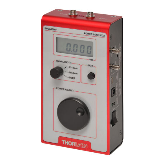
- Page 1 EVOA1550F & EVOA1550A Electronic Variable Optical Attenuators User Guide...
-
Page 2: Table Of Contents
Maintenance & Repair ..........11 Chapter 6 Specifications............12 6.1. General Specifications ........... 12 6.2. Mechanical Drawings .......... 13 Chapter 7 Regulatory ..............14 Chapter 8 Certificate of Compliance ........15 Chapter 9 Thorlabs Worldwide Contacts ........ 16 TTN095737-D02... -
Page 3: Chapter 1 Warning Symbol Definitions
Electronic Variable Optical Attenuators Chapter 1: Warning Symbol Definitions Chapter 1 Warning Symbol Definitions Below is a list of warning symbols you may encounter in this manual or on your device. Symbol Description Direct Current Alternating Current Both Direct and Alternating Current Earth Ground Terminal Protective Conductor Terminal Frame or Chassis Terminal... -
Page 4: Chapter 2 Safety
Only with written consent from Thorlabs may changes to single components be carried out or components not supplied by Thorlabs be used. This product has been tested and found to comply with the limits according to IEC 61326-1 for using connection cables shorter than 3 meters (9.8 feet). -
Page 5: Chapter 3 Introduction & Quick Start
These EVOAs are designed for use with standard single mode fiber (e.g. SMF-28e+) and accept either FC/PC connectors (Item # EVOA1550F) or FC/APC connectors (Item # EVOA1550A). The wavelength selector switch accesses calibrated settings for 1310 nm and 1550 nm, and also provides a position which the user can calibrate for any wavelength from 1250 nm to 1625 nm. -
Page 6: Fiber Interface & Utility Panels
Electronic Variable Optical Attenuators Chapter 3: Introduction & Quick Start 3.3. Fiber Interface & Utility Panels Output Input Bulkhead Bulkhead Connector Label Figure 2 Fiber Interface Panel (Top View) 2.1 mm Charging Jack Charging Indicators for Included Power Green: Fully Charged Supply Yellow: Charging USB Mini-B... -
Page 7: Quick Start Guide
Electronic Variable Optical Attenuators Chapter 3: Introduction & Quick Start 3.4. Quick Start Guide ESD CAUTION The components inside these products are sensitive to electrostatic discharge (ESD). Take all appropriate precautions, including grounding personnel and equipment, before making any connections to the unit. In the box, you should find the EVOA and its power supply with a 2.1 mm coaxial plug that matches the power input jack on the side of the unit. -
Page 8: Chapter 4 Operating Instructions & Details
Electronic Variable Optical Attenuators Chapter 4: Operating Instructions & Details Chapter 4 Operating Instructions & Details 4.1. Overview This chapter provides deeper details about the EVOA and its operation. To get started with using the EVOA, refer instead to the Quick Start Guide (Section 3.4). -
Page 9: Fiber Connections
LED indicates that charging is in progress, while a green LED indicates that charging is complete. If both LEDs are lit, there is a battery fault. Please contact Thorlabs’ tech support (techsupport@thorlabs.com) if this occurs. When the power is switched on, the attenuation will be set at the value determined by the position of the manual power adjustment knob. -
Page 10: Attenuation Control
Electronic Variable Optical Attenuators Chapter 4: Operating Instructions & Details Follow these simple steps to calibrate the USER position: Switch the wavelength selector knob to the USER position. Send an optical input into the input bulkhead at the wavelength of interest. -
Page 11: Power Lock
Electronic Variable Optical Attenuators Chapter 4: Operating Instructions & Details The modulation input allows the user to control the attenuation by applying an AC or DC voltage of up to 4.9 V. AC drive signals of up to 1 kHz can be used for high-speed modulation of the output power. -
Page 12: Chapter 5 Maintenance & Repair
FCC-7020 Fiber Connector Cleaner (sold separately). The end faces of the EVOA’s internal connectors can be easily damaged by dirty fiber ends, and if damage occurs, the unit will need to be returned to Thorlabs for repair. The EVOA’s internal connectors can be cleaned using, for example, Thorlabs’... -
Page 13: Chapter 6 Specifications
Electronic Variable Optical Attenuators Chapter 6: Specifications Chapter 6 Specifications 6.1. General Specifications Item # EVOA1550F EVOA1550A 2.0 mm Narrow Key 2.0 mm Narrow Key Fiber Interfaces FC/PC FC/APC Wavelength Range 1250 - 1625 nm 200 mW (Max) Input Power Absolute Maximum: 250 mW Minimum: 1.5 dB (Typ.) -
Page 14: Mechanical Drawings
Electronic Variable Optical Attenuators Chapter 6: Specifications 6.2. Mechanical Drawings 3.1 mm (0.12") 55.2 mm (2.17") 166.9 mm (6.57") 161.0 mm (6.34") 87.0 mm (3.43") 93.2 mm (3.67") Rev B, September 5, 2017 Page 13... -
Page 15: Chapter 7 Regulatory
Thorlabs or your nearest dealer for further information. Waste Treatment is Your Own Responsibility If you do not return an “end of life” unit to Thorlabs, you must hand it to a company specialized in waste recovery. Do not dispose of the unit in a litter bin or at a public waste disposal site. -
Page 16: Chapter 8 Certificate Of Compliance
Electronic Variable Optical Attenuators Chapter 8: Certificate of Compliance Chapter 8 Certificate of Compliance Rev B, September 5, 2017 Page 15... -
Page 17: Thorlabs Worldwide Contacts
Chapter 9 Thorlabs Worldwide Contacts For technical support or sales inquiries, please visit us at www.thorlabs.com/contact for our most up-to-date contact information. USA, Canada, and South America UK and Ireland Thorlabs, Inc. Thorlabs Ltd. sales@thorlabs.com sales.uk@thorlabs.com techsupport@thorlabs.com techsupport.uk@thorlabs.com Europe Scandinavia... - Page 18 www.thorlabs.com...
Need help?
Do you have a question about the EVOA1550F and is the answer not in the manual?
Questions and answers