Table of Contents
Advertisement
Advertisement
Table of Contents

Related Manuals for THORLABS ERM100


Summary of Contents for THORLABS ERM100
- Page 1 Extinction Ratio Meter ERM100 Operation Manual 2018...
- Page 2 Version: Date: 10-Jul-2018 Item No.: M0009-510-309 Copyright © 2018 Thorlabs...
-
Page 3: Table Of Contents
3.9 Measurement consideration 4 Remote Operation 4.1 Installing Software 4.1.1 Install NI Visa 4.2 4.1.2 Install Remote Control Application 4.1.3 Install Instrument Communicator 4.1.4 Install Firmware Upgrade Wizard 4.1.5 Install NI Instrument Drivers 4.2 Connect the ERM100 4.3 Remote Control Application... - Page 4 6.2.5 General System Commands 6.3 Status Reporting 6.3.1 Status Structure 6.3.2 Register Description 6.4 Certifications and Compliances 6.5 Warranty 6.6 Copyright and Exclusion of Reliability 6.7 Thorlabs 'End of Life' Policy (WEEE) 6.8 List of Acronyms 6.9 Thorlabs Worldwide Contacts...
-
Page 5: Foreword
Paragraphs preceded by this symbol explain hazards that could damage the instrument and the connected equipment or may cause loss of data. Note This manual also contains "NOTES" and "HINTS" written in this form. Please read this advice carefully! © 2018 Thorlabs... -
Page 6: General Information
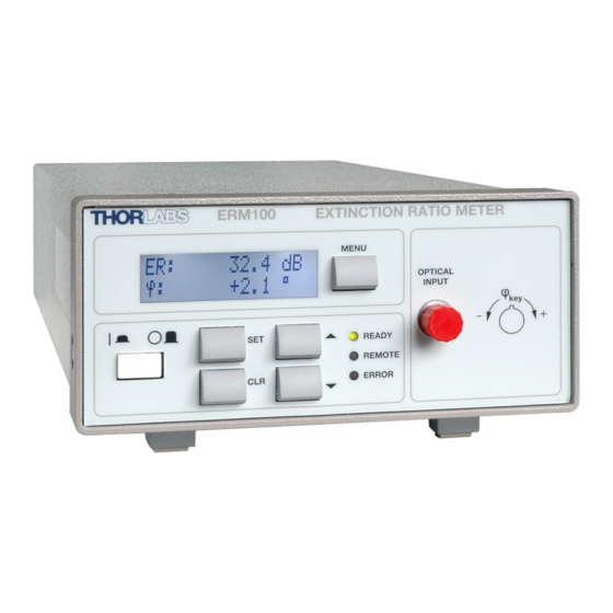
ERM100 General Information The ERM100 Benchtop Extinction Ratio Meter is designed to analyze the ER of laser light in a polarization maintaining fiber for any kind of alignment applications like connectorization of PM fibers or pigtailing of laser diodes with PM fibers. -
Page 7: Ordering Codes And Accessories
USB cable according the USB 2.0 specification 1.3.2 Software Requirements ® The ERM100 software (CD1.1) is compatible with Windows XP (32-bit) SP3 operating sys- tem. A NI-VISA engine V4.2 or higher must be installed. This NI-VISA engines comes with the Thorlabs ERM100 installation CD. -
Page 8: Installation
After switching on the unit, the display will show the device version and then jump to the opera- tion screen. The ERM100 is immediately ready to use after turning on. The rated accuracy is reached, how- ever, after a warming-up time of approx. 15 minutes. -
Page 9: Operating Instruction
3 Operating Instruction Operating Instruction Operating Elements Front Panel Rear Panel © 2018 Thorlabs... -
Page 10: Operation And Settings
ERM100 Operation and Settings The ERM100 is controlled by five buttons on the front. A LC display on the front panel shows all measurement data in various display configurations. All necessary settings can be easily done using the control buttons and will be shown on the display. -
Page 11: Menu
'MENU' button. To return to 'Main Display Mode' press the 'MENU' but- ton again. The ERM100 being in 'Menu Mode' is indicated by an arrow in the upper right corner of the display pointing to the 'MENU' button. -
Page 12: Serial Number
ERM100 Remote The ERM100 is operated by the remote interface. The 'REMOTE' LED on the ERM100 front is on. The front panel can not change settings but this menu entry can be used to switch back to local mode. To switch back to local mode press the 'SET' button to enter the edit mode of the 'REMOTE STATE' menu entry. -
Page 13: Bootloader Version
If the 'CLR' (Clear) button is pressed within these 3 seconds, the instrument is set to local mode. If the ERM100 is in remote control state with local lockout and you try to change any setting for 3 seconds a remote with local lockout message display is shown. -
Page 14: Measurement Procedure
PM fiber patch cords. The ERM100 can be used to couple linear polarized light into the slow (or fast) axis of a polari- zation maintaining (PM) fiber as well as align the connectors key to the slow (or fast) axis of the PM fiber. -
Page 15: Alignment Of A Laser Diode To A Pm Fiber
The alignment of a laser diode to a PM fiber can be done in the following way: 1. The output of the fiber is entered to the input of the ERM100 and the unit is switched on. 2. Toggle to the ER display by pressing the button 'SET'. -
Page 16: Alignment Of A Pmf Patchcord
Therefore, a broadband source like a SLED or ASE is more suitable for this task. The Extinc- tion Ratio measurement of a PM fiber with a SLED can be done in the following way: 1. The output of the PM fiber is entered to the input of the ERM100 and the ERM100 is switched on. -
Page 17: Measurement Consideration
99.98 99.99 99.998 ER [dB] 12.8 20.0 23.0 30.0 33.0 35.0 40.0 43.0 50.0 If the DOP is a problem for the ER measurement a more complex measurement system like Thorlabs' Polarization Measurement System PAX57xx is required. © 2018 Thorlabs... -
Page 18: Remote Operation
Write Your Own Application Attention Prior to connect the ERM100 first time to a PC, please install the software from the delivered with the ERM100 CD! Otherwise, a proper operation is impossible. Installing Software The delivered with ERM100 CD includes: ·... -
Page 19: Install Ni Visa
® ® If you want to operate the ERM100 from a Windows Vista or Windows 7 operating system, you need to install a NI VISA Runtime, version 5.0.2 or higher. You can download it from Na- tional Instruments' web site www.ni.com/visa/. - Page 20 ERM100 © 2018 Thorlabs...
- Page 21 You may choose "Restart later" and continue with the installation of Remote Control Applica- tion, however you need to restart the computer prior to connect the ERM100 first time for a proper operation. Otherwise, the ERM100 won't be recognized in a correct way.
-
Page 22: Install Remote Control Application
ERM100 4.1.2 Install Remote Control Application Click "I accept..." if you do so, then click "Next >>": © 2018 Thorlabs... - Page 23 4 Remote Operation Click "Finish" to complete the installation. Note If the computer has not been restarted after NI VISA installation, please reboot now. © 2018 Thorlabs...
-
Page 24: Install Instrument Communicator
ERM100 4.1.3 Install Instrument Communicator Click "I accept..." if you do so, then click "Next >>": © 2018 Thorlabs... -
Page 25: Install Firmware Upgrade Wizard
4 Remote Operation Click "Next >>" to finish the installation. 4.1.4 Install Firmware Upgrade Wizard This wizard is an easy-to-use tool for uploading a new firmware version. © 2018 Thorlabs... - Page 26 ERM100 Click "I accept..." if you do so, then click "Next >>": © 2018 Thorlabs...
- Page 27 4 Remote Operation Click "Next >>" to finish the installation. © 2018 Thorlabs...
-
Page 28: Install Ni Instrument Drivers
ERM100 4.1.5 Install NI Instrument Drivers This topic installs ERM100 instrument drivers for different programming interfaces. For details, please see section Write Your Own Application. © 2018 Thorlabs... -
Page 29: Connect The Erm100
Connect the ERM100 to the PC using the provided USB 2.0 cable (A to B). The Found New Hardware Wizard comes up. It will recognize the ERM100 twice - as a USBTMC (USB Test and Measurement Class) and as a DFU (Device Firmware Upload) cap- able device. - Page 30 ERM100 Check the box "No, not this time", then "Next >>" to continue © 2018 Thorlabs...
- Page 31 Check the box "No, not this time", then "Next >>" to continue ® Under Windows 7 operating system, the device recognition and driver install is more simple - after connect, a single screen appears during driver installation, after completion it states: © 2018 Thorlabs...
-
Page 32: Remote Control Application
ERM100 The ERM100 drivers are installed now and your device is ready to be remotely operated. Remote Control Application The Remote Control Application is an easy-to-use simple data logger. Make sure the ERM100 is connected and recognized. Start the application from the "Start" but- ton: Click "Connect", a dialog screen comes up. - Page 33 4 Remote Operation The logged data can be saved in *.csv file format. © 2018 Thorlabs...
-
Page 34: Write Your Own Application
NI VISA instrument driver C:\Program Files\IVI Foundation\VISA\WinNT\Bin\ERM100_Drv_32.dll Note This instrument driver is required for all development environments! NI VISA instrument driver online help: C:\Program Files\IVI Foundation\VISA\WinNT\Thorlabs ERM100\manual\ERM100_Drv.hlp C:\Program Files\IVI Foundation\VISA\WinNT\Thorlabs ERM100\manual\ERM100_Drv.txt C:\Program Files\IVI Foundation\VISA\WinNT\Thorlabs ERM100\manual\ERM100_Drv_VB.txt Matlab / LabVIEW programming Function Panel C:\Program Files\IVI Foundation\VISA\WinNT\Thorlabs ERM100\ERM100_Drv.fp... -
Page 35: Maintenance And Service
DFU (device firmware upgrade) wizard from the distribution CD. Connect the ERM100 to a USB port of your PC, switch it on and launch the DFU wizard from the Start button: Click "Next >" to continue: © 2018 Thorlabs... - Page 36 ERM100 Select the ERM100 firmware file, click "Next >": © 2018 Thorlabs...
- Page 37 5 Maintenance and Service The wizard has switched the ERM100 to DFU mode, but so far no DFU device driver has been installed yet. As for this reason, the wizard cannot find a DFU device and an Error message comes up. Don't click nor to Yes nor to No! Please note, that at the same time in the background a "Found New Hardware Wizard"...
- Page 38 ERM100 After finishing the DFU driver installation, the above screen closes this way getting you back to Error screen - now click "Yes" to continue. © 2018 Thorlabs...
-
Page 39: Version Information
· bootloader version from the display. Prior to contact Thorlabs, please retrieve this information and keep it ready. Troubleshooting In case that your ERM100 shows malfunction please check the following items: Unit does not work at all (no display at the front): Ø... -
Page 40: Replacing Mains Fuses
Thorlabs prior to return the ERM100 for checkup and repair. Replacing Mains Fuses The ERM100 optical power meter operates at a line voltage range of 90 V … 264 V. The two power input fuses are externally accessible. If they have opened due to line distortions or other causes, they can be replaced from the rear without opening the unit. - Page 41 3. Replace the defective or wrong fuses and press in the fuse holder until locked on both sides. Fuse type T0.8A 250V (800 mA, time-lag, 250V) Note The fuses must meet IEC specification 60127-2/III, time characteristic: time-lag (T), 250V AC, size 5 x 20 mm. © 2018 Thorlabs...
-
Page 42: Appendix
) for input power > -30dBm ) Dynamic range depends on specific wavelength ) others on request ) non condensing All technical data are valid at 23 ± 5°C and 45 ± 15% rel. humidity (non condensing) © 2018 Thorlabs... -
Page 43: Instrument Driver Command Reference
Selftest query (see also IEEE488.2-1992-§10.38 and chapter ‘Selftest Results’ in this document). A return value of ‘0’ means success. Operation Complete Command Command syntax: *OPC Description: Sets the ‘OPC’ bit in the ‘Standard Event Status Register’ (see also IEEE488.2-1992-§10.18). © 2018 Thorlabs... - Page 44 This command resets the device. (see also IEEE488.2-1992- §10.32). Service Request Enable Command Command syntax: *SRE <DECIMAL NUMERIC PROGRAM DATA> Description: Sets the device’s Service Request Enable Register (see also IEEE488.2-1992-§10.34 and chapter ‘Status Reporting’ in this document). © 2018 Thorlabs...
- Page 45 Clear Status Commend Command syntax: *CLS Prerequisite: None Description: Clears the following device’s status registers (see also IEEE488.2-1992-§10.3): · Standard Event Status Register · Device Error Event Register · Device Operation Event Register · Device Error Queue © 2018 Thorlabs...
-
Page 46: Measurement Commands
'+Inf' for the ER and '0.0' for the angle are returned and an error is insert into the error queue. The reset sets the ER value to '+Inf' and the angle to '0.0'. © 2018 Thorlabs... -
Page 47: Device Setup Commands
Queries the currently used wavelength [nm]. Query Wavelength Range Command syntax: :WAVEL:RNG? Response syntax: minimum settable wavelength [nm]: <NR3 NUMERIC RESPONSE DATA>, maximum settable wavelength [nm]: <NR3 NUMERIC RESPONSE DATA>, currently used wavelength [nm]: <NR3 NUMERIC RESPONSE DATA> Description: Queries wavelength range. © 2018 Thorlabs... -
Page 48: Device Status Commands
Queries the device’s Error Event Enable Register (see also chapter ‘Status Reporting’ in this document). Query Device Operation Condition Register Command syntax: :STAT:OPER:CND? Response syntax: <NR1 NUMERIC RESPONSE DATA> Description: Queries the device’s Operation Condition Register (see also chapter ‘Status Reporting’ in this document). © 2018 Thorlabs... -
Page 49: General System Commands
Error text <ARBITRARY ASCII RESPONSE DATA> Description: Queries the device’s error queue (see also: chapter ‘Error Report- ing’ in this document). Query Descriptive Device Information Command syntax: :SYST:INFO? Response syntax: <ARBITRARY ASCII RESPONSE DATA> Description: Queries descriptive device information. © 2018 Thorlabs... -
Page 50: Status Reporting
ERM100 Status Reporting 6.3.1 Status Structure The device uses a status reporting structure like it is defined in IEEE488.2-1992-§11. The fig- ure below shows the complete structure. © 2018 Thorlabs... -
Page 51: Register Description
Sensor motor speed low Sensor motor speed high Device Operation Status Structure The Device Operation Status Structure reflects device states. Bits in the according event re- gister are rising edge and falling edge triggered. Bit # Mnemonic Description reserved 15..0 © 2018 Thorlabs... - Page 52 Adjustment data set invalid by user Device setup data corrupt Internal calculation error Authentication required for operation Authentication failed Operation is not allowed in SERVICE-MODE Operation is allowed in SERVICE-MODE only Erroneous HEX record Erroneous sensor checksum Erroneous converter adjustment checksum © 2018 Thorlabs...
- Page 53 6 Appendix Error Description Erroneous key offset checksum I²C: Illegal START/STOP condition I²C: Slave adress not acknowledged (Not a valid bus adress?) I²C: Incomplete write operation (Slave rejected to receive all data in the buffer) I²C: Arbitration lost © 2018 Thorlabs...
-
Page 54: Certifications And Compliances
Emissions, which exceed the levels required by these standards, may occur when this equipment is connected to a test object. Performance Criterion C was reached at additional test levels according to EN 61326-1:2006 table 2. Replaces 73/23/EEC, amended by 93/68/EEC © 2018 Thorlabs... -
Page 55: Warranty
Thorlabs warrants material and production of the ERM100 for a period of 24 months starting with the date of shipment. During this warranty period Thorlabs will see to defaults by repair or by exchange if these are entitled to warranty. -
Page 56: Copyright And Exclusion Of Reliability
ERM100 Copyright and Exclusion of Reliability Thorlabs has taken every possible care in preparing this document. We however assume no li- ability for the content, completeness or quality of the information contained therein. The content of this document is regularly updated and adapted to reflect the current status of the hardware and/or software. -
Page 57: Thorlabs 'End Of Life' Policy (Weee)
Waste treatment on your own responsibility If you do not return an “end of life” unit to Thorlabs, you must hand it to a company specialized in waste recovery. Do not dispose of the unit in a litter bin or at a public waste disposal site. -
Page 58: List Of Acronyms
The following acronyms and abbreviations are used in this manual: Amplified Spontaneous Emission Direct Current Distributed Feedback (laser) Device Firmware Update Degree Of Polarization Device Under Test Extinction Ration Polarization-Maintaining Polarization-Maintaining Fiber SLED Super-Luminescent Emitting Diode Universal Serial Bus © 2018 Thorlabs... -
Page 59: Thorlabs Worldwide Contacts
6 Appendix Thorlabs Worldwide Contacts For technical support or sales inquiries, please visit us at www.thorlabs.com/contact for our most up-to- date contact information. USA, Canada, and South America UK and Ireland Thorlabs, Inc. Thorlabs Ltd. sales@thorlabs.com sales.uk@thorlabs.com techsupport@thorlabs.com techsupport.uk@thorlabs.com Europe...
Need help?
Do you have a question about the ERM100 and is the answer not in the manual?
Questions and answers