Advertisement
Quick Links
Advertisement

Related Manuals for THORLABS ELL8K


Summary of Contents for THORLABS ELL8K
- Page 1 ELL8K(/M) Rotation Stage Kit Operating Manual Original Instructions...
- Page 2 Regulatory ........................13 6.1. Declarations of Conformity ................... 13 6.1.1. For Customers in Europe ....................13 6.1.2. For Customers In The USA ................... 13 6.2. Waste Electrical and Electronic Equipment (WEEE) Directive ......14 Chapter 7 Thorlabs Worldwide Contacts .................. 15...
- Page 3 Chapter 1 Safety For the continuing safety of the operators of this equipment, and the protection of the equipment itself, the operator should take note of the Warnings, Cautions and Notes throughout this handbook and, where visible, on the product itself. SHOCK WARNING Given when there is a risk of electric shock.
- Page 4 2.1. Introduction The ELL8 Rotation Stage is part of the Thorlabs series of resonant piezo motor circuits and bare modules for OEM applications. The resonant piezo design of these motors offers fast response times and precise positioning, and are therefore particularly useful in scanning applications.
- Page 5 Do not allow the wires to contact other moving parts. The recommended mounting orientation is horizontal. Two mounting brackets are shipped with the ELL8K kit to allow mounting to a standard 1” or 25 mm pitch optical table or breadboard.
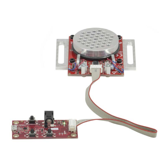
- Page 6 Chapter 2: Description Figure 2 ELL8 with components fitted Figure 3 Fixing the ELL8K to the work surface 1. Using the M3 x 6 mm (6-32 x ¼”) bolts supplied, fix the mounting brackets to the circuit board as shown above.
- Page 7 3. Connect the stage to a 5V supply and switch ‘ON’. (A 5V PSU is supplied with the ELL8K). 4. Connect the unit to your PC if required, and wait for the drivers to be installed.
- Page 8 ELL8K Rotation Stage Evaluation Kit Chapter 3: Operation 3.2. Controlling the Stage The stage can be controlled in three ways; via the handset, by the Elliptic software running on a PC, or by writing a custom application using the messages described in the communications protocol document. Homing and Jogging functionality can also be accessed by applying voltages to the digital lines on Connector J1.
- Page 9 On power up the stage will move while the unit checks the sensors and then searches for the home position. The hand-held controller supplied with the ELL8K Evaluation Kit features two buttons (marked FW and BW) that allow control of the stage position. The handset also provides for connection to the host PC and to the external 5V power supply.
- Page 10 3.2.2. Software Control When connected to the host PC, the stage can be controlled remotely, via the Elliptec software. 1. Download the Elliptic software from the downloads section at www.thorlabs.com. Double click the saved .exe file and follow the on-screen instructions.
- Page 11 ELL8K Rotation Stage Evaluation Kit Chapter 3: Operation The communication bus allows multi-drop communication with speeds at 9600 baud, 8 bit data length, 1 stop bit, no parity. Protocol data is sent in ASCII HEX format, while module addresses and commands are mnemonic character (no package length is sent).
- Page 12 ELL8K Rotation Stage Evaluation Kit Chapter 3: Operation Connector J1 Pin Out TYPE FUNCTION Ground ODTX - open drain transmit 3.3V TTL RS232 RX receive - 3.3V TTL RS232 In Motion, open drain active low max 5mA JOG/Mode, active low max 5V...
- Page 13 ELL8K Rotation Stage Evaluation Kit Chapter 3: Operation 3.3. Frequency Search Due to load, build tolerances and other mechanical variances, the default resonating frequency of a particular motor may not be that which delivers best performance. A frequency search can be performed using the Main...
- Page 14 ELL8K Rotation Stage Evaluation Kit Chapter 4: Troubleshooting and FAQ Chapter 4 Troubleshooting and FAQ Stage is moving back and forth after power up If the digital line “bw” is driven low before powering up the stage, the module will go into calibration mode.
- Page 15 ELL8K Rotation Stage Evaluation Kit Chapter 5: Specifications Chapter 5 Specifications General Specifications Travel 360° Continuous Minimum Life Time 100 km (600,600 revolutions). Max Velocity 1.4 Hz (504 °/s) ±0.6 Hz Max Acceleration 3.25 Hz/s (1170 °/s/s) Repeatability 434 µrad (0.025°) Homing/Positioning Accuracy 288.0 µrad (0.0165°)
- Page 16 ELL8K Rotation Stage Evaluation Kit Chapter 6: Regulatory Chapter 6 Regulatory 6.1. Declarations of Conformity 6.1.1. For Customers in Europe 6.1.2. For Customers In The USA This equipment has been tested and found to comply with the limits for a Class A digital device, persuant to part 15 of the FCC rules.
- Page 17 Waste Treatment is Your Own Responsibility If you do not return an “end of life” unit to Thorlabs, you must hand it to a company specialized in waste recovery. Do not dispose of the unit in a litter bin or at a public waste disposal site.
- Page 18 ELL8K Rotation Stage Evaluation Kit Chapter 7: Thorlabs Worldwide Contacts Chapter 7 Thorlabs Worldwide Contacts For technical support or sales inquiries, please visit us at www.thorlabs.com/contact for our most up-to- date contact information. USA, Canada, and South America UK and Ireland Thorlabs, Inc.
- Page 19 www.thorlabs.com...
Need help?
Do you have a question about the ELL8K and is the answer not in the manual?
Questions and answers