Table of Contents
Advertisement
Quick Links
Advertisement
Table of Contents

Related Manuals for PXM PX370-L0


Summary of Contents for PXM PX370-L0
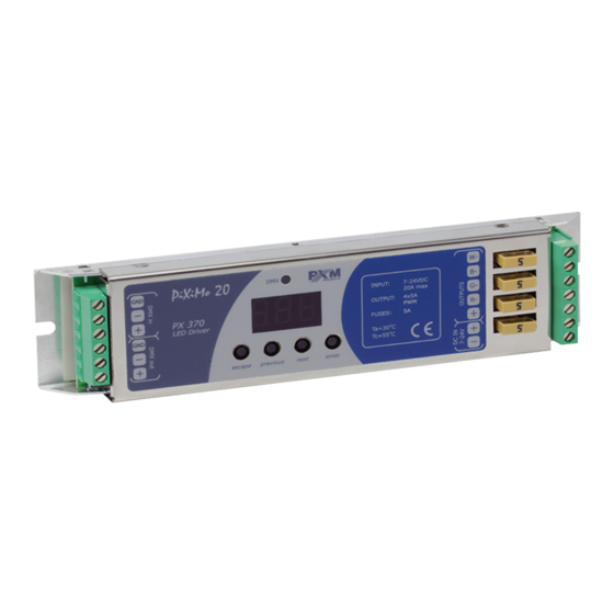
- Page 1 PX370 PX370-L0 Driver LED C.V. 4 x 5A User manual...
-
Page 2: Table Of Contents
Table of Contents 1 Description....................4 2 Safety conditions..................5 3 Connectors and control elements............6 4 Designation of displayed messages............6 5 Button features...................8 6 Group DMX address settings..............9 7 Individual DMX address settings............10 8 Color settings mode................11 9 No DMX signal response................14 9.1 Description of programs..................16 10 Master / Slave function................18 11 White balance..................19... - Page 3 Manufacturer reserves the right to make modifications in order to improve device operation. PXM Marek Żupnik sp.k. Podłęże 654 tel. +48 12 385 83 06 32-003 Podłęże mail: info@pxm.pl Rev.1-5 BDO register number 000005972 www.pxm.pl 27.09.2021...
-
Page 4: Description
Description The PX370 driver is designed to control LEDs. Built-in DMX receiver allows for controlling 4 channels (R, G, B, W) directly with the DMX protocol. Wide range of power supply voltage and high current carrying capacity outputs permit a control of large quantities of LEDs. PX370 can be either controlled by DMX, and act independently. -
Page 5: Safety Conditions
Safety conditions PX370 Driver LED C.V. 4 x 5A is a device powered with safe voltage 7 – 24V; however, during its installation and use the following rules must be strictly observed: 1. The device may only be connected to 7 – 24V DC with current-carrying capacity compatible with technical data. -
Page 6: Connectors And Control Elements
Connectors and control elements display control outputs DMX input DMX output power supply programming keys 7 - 24V DC Designation of displayed messages DMX address of a device – a basic item in the MENU setting parameters for all channels simultaneously setting parameters for each channel individually inverting the meter display 180 degrees DMX address setting... - Page 7 Lightness / Color control mode RGB control mode RGBW control mode RGB Dimmer control mode RGBW Dimmer control mode HSL control mode – Hue / Saturation / Lightness effect control mode dynamic white mode all outputs at 100% all outputs off scene program no.
-
Page 8: Button Features
program playback speed level of steps change smoothness in the program red color during scene programming green color during scene programming blue color during scene programming white color during scene programming basic frequency of brightness control screen blanking memory error message restore default device settings menu restore default device settings menu Button features... -
Page 9: Group Dmx Address Settings
Group DMX address settings The menu of the PX370 driver allows for setting the DMX address within a range between 1 and 505 – 511 depending on work mode of device. For example in RGBW mode it occupies four consecutive DMX addresses. If start address is set to 509, the last channel is occupied by address 512. -
Page 10: Individual Dmx Address Settings
Individual DMX address settings The PX370 module has an option that allows for changing individual settings. It enables assigning any DMX address to every output channel. The simplest example of implementation of this function is to control the lightness of one-color LEDs connected to all outputs. In such case, the same address must be assigned to all channels so that all outputs are controlled by one slider on the control panel. -
Page 11: Color Settings Mode
Color settings mode ENTER ENTER NEXT The PX370 driver can operate in different control ENTER modes. Depending on the selected mode, the device NEXT takes up a different numbers of channels, possible modes: The HSL mode (Hue, Saturation, Lightness) operates on three NEXT channels, responsible for hue, saturation and lightness NEXT... - Page 12 The EFF mode – effects control – it is available on 8 DMX channels and allows to choose the right effect and parameters (description of the EFF mode is on the next page): Channel 1 – red color Channel 2 – green color Channel 3 –...
- Page 13 Description guide of EFF mode settings CHANNEL 1 CHANNEL 2 CHANNEL 3 CHANNEL 4 CHANNEL 6 CHANNEL 7 CHANNEL 8 CHANNEL 5 MODE GREEN BLUE WHITE SPEED FADE BRIGHTNESS <0–7> Program 1 <8–15> Program 2 <16–23> Program 3 <24–31> Program 4 <32–39>...
-
Page 14: No Dmx Signal Response
No DMX signal response This function is used both to protect the installation against the DMX signal loss and to obtain control over LEDs without connecting an external controller. Once it is activated, if there is no DMX signal the module will realize a desired function independently. - Page 15 P01 – P18 – choosing a ready program provided in the device software. For each program it is possible to set the speed (SPd) of the effects reproduction on range 0,1 – 99,9s and smoothness of change of steps (FAd) in range 0 –...
-
Page 16: Description Of Programs
9.1 Description of programs The following tables show the values for each output channel (R, G, B, W) in programs from 1 up 18 (P01 – P18). The value 255 corresponds to the maximum lightness level on a given channel, 127 – 50% of power level, 0 –... - Page 17 Step 1 Step 2 Step 3 Step 4...
-
Page 18: Master / Slave Function
10 Master / Slave function The PX370 module has a built-in DMX-512 receiver and can be controlled from any desktop or controller running in this standard. Moreover, it is equipped with a programmable function of response to no DMX signal (noS). With 18 built-in default programs, it is possible to obtain interesting effects without an external controller. -
Page 19: White Balance
11 White balance Sometimes, there can be problems with getting white color on the RGBW series LEDs. This may be a result of using diodes with different technical parameters. For this reason, the PX370 module is equipped with a white balance function. -
Page 20: Limiting The Output Power
12 Limiting the output power The white balance parameter, apart from its original functionality, can also be used to limiting the output power of the driver. It works linearly and in a percentage way limits the output power of a given channel. For example, if the bLr parameter is set on 50, it means that by the DMX control and no signal mode this value can not be exceeded. -
Page 21: Smooth
13 Smooth The driver is equipped with a smooth option. Smooth feature allows for smooth changes in lightness and color. When it is set to On the transition between successive DMX values sent to the lamp (e.g. corresponding to changes in lightness) are smooth with no visible twitches, which prevents the common light “vibrations”... - Page 22 NOTE! In the L0 version, the smoothing settings are presented below. Information whether the device is the L0 version is displayed during device start-up. By default, the Sth option is enabled at level 003. The options are: • Off – smoothing disabled, 001 –...
-
Page 23: Selection Of Control Curve
14 Selection of control curve The driver has implemented the option of choosing one of three output control curves: linear Lin – the output values is linearly proportional to the control • value, • DALI – dAL, exponential EP1 with exponent 2. •... -
Page 24: Light Control Frequency
15 Light control frequency The Frq function allows for setting the basic control frequency for the LEDs. This function is extremely useful in applications for the television industry. By applying the "flicker free" technology, it is possible to avoid the unpleasant flickering effect which is caused by improper signal synchronization that controls the LEDs. -
Page 25: Screen Saving (Screen Blanking)
16 Screen saving (screen blanking) The device is equipped with a feature that allows for turning off the backlight. This option is marked with the SCr sign. With this feature, the display is turned off after about 60s (if the keys of the device are not pressed). Of course, the device continues its operation without interfering with other parameters. -
Page 26: Restore Default Settings
17.1 Restore default settings To restore the device to its default settings, press and hold the previous key while switching on the device. One of the messages that will be displayed will say dFl, which means successful restoring to default settings (the previous key has to be held down while powering on the device, until the dFl message is displayed). -
Page 27: Error Message
NOTE! In the device version L0, restoring the factory settings is available from the device menu. Information whether the device is the L0 version is displayed during device start-up. ENTER 4 x NEXT Pressed ENTER ENTER 17.2 Error message The device is equipped with a built-in memory work control function. If there are problems with the memory operation on the PX370 display, the Err message appears –... -
Page 28: Display Flip Function
18 Display flip function As the driver should be installed (As far as possible) in a small distance from the controlled LEDs, the lack of space may force the necessity of mounting the device upside-down. In such case the displayed messages become illegible, that does not have the influence on device operation, but makes the programming much more difficult. -
Page 29: Device Update
19 Device update The update is possible using the PX313 USB / RS485 In device – details can be found in the manual for this module. The device update was also presented in detail on our YouTube channel. https://www.youtube.com/watch?v=lSlFGeXVR_k... -
Page 30: Dmx Signal Connecting
20 DMX signal connecting PX370 have to be connected to DMX line in serial mode, with no branches on DMX control cable. That means that DMX line, from the signal source, must be connected to DMX IN pins of PX370 and later, directly from DMX OUT pins to the next device in DMX chain. - Page 31 List of RDM parameters supported by the PX370: Parameter name Description SUPPORTED_PARAMETERS 0x0050 all supported parameters description of additional PARAMETER_DESCRIPTION 0x0051 parameters DEVICE_INFO 0x0060 information concerning the device SOFTWARE_VERSION_LABEL 0x00C0 firmware version of the device DMX starting address of the DMX_START_ADDRESS * / 0x00F0 device;...
- Page 32 Parameter name Description DMX_PERSONALITY_ DESCRIPTION / description of individual 0x00E1 PERSONALITY_ operational modes DESCRIPTION DEVICE_HOURS ** 0x0400 operating time counted in hours BALANCE_RED * / value of control level of red channel 0x8011 BALANCE_CH1 * balance BALANCE_GREEN * / value of control level of green 0x8012 BALANCE_CH2 * channel balance...
- Page 33 Parameter name Description SCREENSAVER_ON/OFF * / 0x8022 settings of screensaver SCREENSAVER_ENABLE * 0x8024 settings of screensaver programs playback speed settings PROGRAM_SPEED * 0x8025 (playing next steps of program) settings of smooth transition PROGRAM_FADE * 0x8026 between following steps of a program BALANCE ON/OFF * / to activate or deactivate the...
-
Page 34: Programming
22 Programming ENTER ENTER ENTER NEXT NEXT ENTER NEXT NEXT ENTER ENTER NEXT NEXT NEXT NEXT NEXT ENTER NEXT NEXT NEXT NEXT ENTER NEXT NEXT NEXT NEXT NEXT NEXT NEXT NEXT NEXT ENTER ENTER NEXT NEXT NEXT ENTER NEXT NEXT ENTER NEXT NEXT... -
Page 35: Connection Scheme
23 Connection scheme controller LED strip RGBW max. 32 devices power supply in DMX line 7 - 24V DC Terminator (rezystor 120 Ohm connected between DMX+ and DMX-) NOTE! That the driver is common anode type device. It is possible to connect lamps with 5-wires cable with a common “+”... - Page 36 Sample connection of warm and cold white LEDs strips for Dynamic White mode warm white LED strip - second set cold white LED strip - second set warm white LED strip - first set cold white LED strip DMX input - first set power supply 7 - 24V DC...
-
Page 37: Dimensions
24 Dimensions 175 mm... -
Page 38: Technical Data
25 Technical data PX370 type PX370-L0 DMX channels RDM protocol support power supply 7 – 24V DC max. current consumption 19mA for 12V DC power consumption without load 17mA for 24V DC output channel number interpolated resolution of output control... - Page 39 Podłęże, 05.04.2019 DECLARATION OF CONFORMITY PXM Marek Żupnik spółka komandytowa Podłęże 654, 32-003 Podłęże we declare that our product: Product name: Driver LED C.V. 4 x 5A Product code: PX370 PX370-L0 meets the requirements of the following standards, as well as harmonised...
Need help?
Do you have a question about the PX370-L0 and is the answer not in the manual?
Questions and answers