Table of Contents
Advertisement
Quick Links
Advertisement
Table of Contents

Subscribe to Our Youtube Channel
Related Manuals for PXM PX370


Summary of Contents for PXM PX370
- Page 1 PX370 LED driver 4x5A/OC User manual...
-
Page 2: Table Of Contents
Table of Contents 1 Description....................4 2 Safety conditions..................5 3 Connectors and control elements............6 4 Designation of displayed messages............6 5 Button features...................8 6 Group DMX address settings..............8 7 Individual DMX address settings.............9 8 Colour settings mode................10 9 No DMX signal response................13 9.1 Description of programs..................15 10 Master / Slave function................16 11 White balance..................17... - Page 3 Manufacturer reserves the right to make modifications in order to improve device operation. PXM Marek Żupnik sp.k. Podłęże 654 tel. +48 12 385 83 06 32-003 Podłęże mail: info@pxm.pl Rev.1-2 BDO register number 000005972 www.pxm.pl 28.11.2018...
-
Page 4: Description
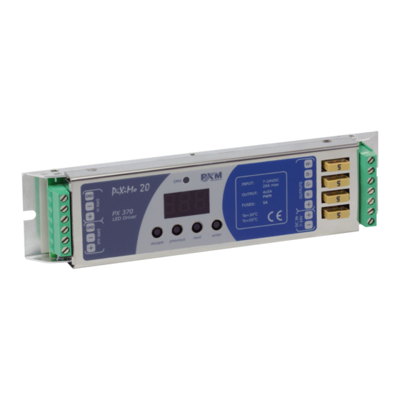
Description The PX370 driver is designed to control LEDs. Built-in DMX receiver allows for controlling 4 channels (R, G, B, W) directly with the DMX protocol. Wide range of power supply voltage and high current carrying capacity outputs permit a control of large quantities of LEDs. -
Page 5: Safety Conditions
Safety conditions PX370 LED Driver 4 x 5A OC is a device powered with safe voltage 7 – 24V; however, during its installation and use the following rules must be strictly observed: 1. The device may only be connected to 7 – 24V DC with current-carrying capacity compatible with technical data. -
Page 6: Connectors And Control Elements
Connectors and control elements DMX-512 input control outputs display power supply DMX-512 output 7 – 24V DC programming keys Designation of displayed messages DMX address of a device – a basic item in the MENU setting parameters for all channels simultaneously setting parameters for each channel individually inverting the meter display 180 degrees DMX address setting... - Page 7 RGB control mode RGBW control mode RGB Dimmer control mode RGBW Dimmer control mode HSL control mode – Hue / Saturation / Lightness effect control mode dynamic white mode all outputs at 100% all outputs off scene programme no. 17 DMX address settings for first channel Master mode on / off number of channels being sent in the Master mode...
-
Page 8: Button Features
– enters the next MENU level and confirms changes made Group DMX address settings The menu of the PX370 driver allows for setting the DMX address within a range between 1 and 505 – 511 depending on work mode of device. -
Page 9: Individual Dmx Address Settings
ENTER NEXT Individual DMX address settings The PX370 module has an option that allows for changing individual settings. It enables assigning any DMX address to every output channel. The simplest example of implementation of this function is to control the lightness of one-color LEDs connected to all outputs. -
Page 10: Colour Settings Mode
Colour settings mode ENTER ENTER NEXT ENTER The PX370 driver can operate in different control NEXT modes. Depending on the selected mode, the device takes up a different numbers of channels, possible modes: NEXT The HSL mode (Hue, Saturation, Lightness) operates on three... - Page 11 The dW – dynamic white – control of 2 channel groups: cold white + warm white, by means of four DMX channels. The first DMX channel is responsible for colour temperature of the first group, and the other channel – for lightness of the group.
- Page 12 Description guide of EFF mode settings CHANNEL 4 CHANNEL CHANNEL CHANNEL CHANNEL CHANNEL CHANNEL CHANNEL 8 1 RED 2 GREEN 3 BLUE WHITE 5 MODE 6 SPEED 7 FADE BRIGHTNESS <0–7> Program 1 <8–15> Program 2 <16–23> Program 3 <24–31> Program 4 <32–39>...
-
Page 13: No Dmx Signal Response
Channel 1 – red colour Channel 2 – green colour Channel 3 – blue colour Channel 4 – white colour Channel 5 – operating mode selection Channel 6 – speed settings (higher value – quicker changes) Channel 7 – fade settings (higher value – smoother transition) Channel 8 –... - Page 14 ENTER ENTER ENTER PREV 2 x NEXT NEXT ENTER NEXT ENTER NEXT NEXT ENTER NEXT NEXT NEXT NEXT P01 – P18 – choosing a ready program provided in the device software. For each program it is possible to set the speed (SPd) of the effects reproduction on range 0,1 –...
-
Page 15: Description Of Programs
9.1 Description of programs The following tables show the values for each output channel (R, G, B, W) in programs from 1 up 18 (P01 – P18). The value 255 corresponds to the maximum lightness level on a given channel, 127 – 50% of power level, 0 –... -
Page 16: Master / Slave Function
Step 10 Master / Slave function The PX370 module has a built-in DMX-512 receiver and can be controlled from any desktop or controller running in this standard. Moreover, it is equipped with a programmable function of response to no DMX signal (noS). -
Page 17: White Balance
Sometimes, there can be problems with getting white colour on the RGBW series LEDs. This may be a result of using diodes with different technical parameters. For this reason, the PX370 module is equipped with a white balance function. This option allows for choosing a correct colour... -
Page 18: Smooth
ENTER ENTER 4 x NEXT ENTER NEXT bLr – value for the red colour (0 – 100) NEXT bLG – value for the green colour (0 – 100) bLb – value for the blue colour (0 – 100) NEXT bLY – value for the white colour (0 – 100) bCn –... -
Page 19: Light Control Frequency
The smooth function may slightly slow down the lamp's response rate to changes in the DMX signal; therefore, it is possible to disable this option. This can be done by checking the parameter and confirming the selection by pressing “enter”. ENTER ENTER 5 x NEXT... -
Page 20: Screen Saving (Screen Blanking)
The frequency value in the upper range (e.g. 1.50 = 1.5kHz) helps to avoid the flickering effects that are visible in video cameras. ENTER 2 x NEXT ENTER NEXT 14 Screen saving (screen blanking) The device is equipped with a feature that allows for turning off the backlight. -
Page 21: Default Settings And Device Errors
In such a case, try to restore the device to its default settings before sending the PX370 to the service center. If, after restoring to its default settings, the device still does not operate correctly, please send it to our service center. -
Page 22: Error Message
15.2 Error message The device is equipped with a built-in memory work control function. If there are problems with the memory operation on the PX370 display, the Err message appears – memory error. In this situation, select the “enter” key. The device will reload the default configuration and upload it to the memory. -
Page 23: Display Flip Function
That is why the PX370 driver has a display flip feature available. It turns the screen 180°. The keys order is reversed as well. -
Page 24: Dmx Signal Connecting
PX370 have to be connected to DMX line in serial mode, with no branches on DMX control cable. That means that DMX line, from the signal source, must be connected to DMX IN pins of PX370 and later, directly from DMX OUT pins to the next device in DMX chain. - Page 25 List of RDM parameters supported by the PX370: Parameter name Description SUPPORTED_PARAMETERS 0x0050 all supported parameters description of additional PARAMETER_DESCRIPTION 0x0051 parameters DEVICE_INFO 0x0060 information concerning the device SOFTWARE_VERSION_LABEL 0x00C0 firmware version of the device DMX starting address of the...
- Page 26 No DMX 0x801C OFF_21 * signal settings of red channel value SCENE_RED * 0x801D for scene saved in PX370 settings of green channel value SCENE_GREEN * 0x801E for scene saved in PX370 settings of blue channel value SCENE_BLUE *...
- Page 27 Parameter name Description settings of blue channel value SCENE_BLUE * 0x801F for scene saved in PX370 settings of white channel value SCENE_WHITE * 0x801F for scene saved in PX370 SCREENSAVER_ON/OFF * 0x8022 settings of screensaver programs playback speed settings PROGRAM_SPEED *...
-
Page 28: Programming
19 Programming ENTER ENTER ENTER NEXT NEXT ENTER NEXT NEXT NEXT NEXT NEXT NEXT ENTER ENTER NEXT NEXT NEXT NEXT NEXT ENTER NEXT NEXT ENTER NEXT NEXT NEXT next page NEXT... - Page 29 previous page ENTER ENTER NEXT NEXT NEXT ENTER NEXT NEXT ENTER NEXT NEXT ENTER NEXT NEXT NEXT NEXT NEXT NEXT ENTER ENTER NEXT NEXT...
-
Page 30: Connection Scheme
20 Connection scheme controller LED strip RGBW max. 32 devices power supply in DMX line 7 - 24V DC Terminator (rezystor 120 Ohm connected between DMX+ and DMX-) Please note that the driver is common anode type device. It is possible to connect lamps with 5-wires cable with a common “+”... - Page 31 Sample connection of warm and cold white LEDs strips for Dynamic White mode warm white LED strip - second set cold white LED strip - second set warm white LED strip - first set cold white LED strip DMX input - first set power supply 7 - 24V DC...
-
Page 32: Dimensions
21 Dimensions 175 mm 22 Technical data type PX370 DMX channels RDM protocol support power supply 7 – 24V DC max. current consumption 19mA for 12V DC power consumption without load 17mA for 24V DC output channel number control accuracy... - Page 33 Master mode weight 0.1kg width: 175mm dimensions height: 42mm depth: 26mm...
- Page 34 Podłęże, 05.04.2019 DECLARATION OF CONFORMITY PXM Marek Żupnik spółka komandytowa Podłęże 654, 32-003 Podłęże we declare that our product: Product name: LED driver 4x5A/OC Product code: PX370 meets the requirements of the following standards, as well as harmonised standards: PN-EN IEC 63000:2019-01...
Need help?
Do you have a question about the PX370 and is the answer not in the manual?
Questions and answers