
Related Manuals for Moxa Technologies ICS-G7 Series


Summary of Contents for Moxa Technologies ICS-G7 Series
- Page 1 ICS-G7526A/G7528A/ G7826A/G7828A-T Series Quick Installation Guide Version 1.2, April 2023 Technical Support Contact Information www.moxa.com/support 2023 Moxa Inc. All rights reserved. P/N: 1802075261014 *1802075261014*...
-
Page 2: Package Checklist
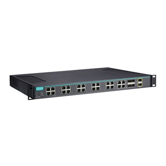
Package Checklist The Moxa ICS-G7526A/G7528A/G7826A/G7828A Series industrial rackmount switches are shipped with the following items. If any of these items are missing or damaged, please contact your customer service representative for assistance. • ICS-G7526A/G7528A/G7826A/G7828A switch • USB cable (Type A male to Type B male) •... - Page 3 1. Model Name 2. System status LEDs 3. 10/100/1000 BaseT(X) port status LEDs 4. 100/1000 Base SFP port status LEDs 5. 10/100/1000 BaseT(X) port 6. 100/1000 Base SFP slot 7. 10/100/1000 BaseT(X) or 100/1000 Base SFP slot combo ports 8. 10 Gigabit Ethernet SFP+ slot 9.
-
Page 4: Wiring The Relay Contact
Connecting the Power Inputs The ICS-G7526A/G7528A/G7826A/G7828A switches support dual redundant power supplies: Power Supply 1 (PWR1) and Power Supply 2 (PWR2). The connections for PWR1 and PWR2 are located on the rear side (shown below). Be sure to use a standard power cord with an IEC C13 connector, which is compatible with the AC power inlet. -
Page 5: The Reset Button
NOTE DO NOT pull out USB Automatic Backup Configurator ABC-02- USB while writing or reading data. The Reset Button Depress the Reset button for five continuous seconds to load the factory default settings. Use a pointed object, such as a straightened paper clip or toothpick, to depress the Reset button. -
Page 6: Specifications
Color State Description The switch’s coupling function is enabled to form a back-up path, or when it’s set CPLR/ as the Tail of the Turbo Chain. GREEN TAIL Blinking Turbo Chain is down The switch disables the coupling function. When the system is importing/exporting data from or to an ABC-02 automatic backup device, the FAULT, MSTR/HEAD, and CPLR/TAIL LEDs will blink in sequence. - Page 7 Layer 3 Switching Static routing, RIP V1/V2, OSPF, DVMRP, PIM-DM, (ICS-G7800A) PIM-SM, PIM-SSM Layer 3 Switching VRRP Redundancy (ICS- G7800A) MIB-II, Ethernet-like MIB, P-BRIDGE MIB, Q- BRIDGE MIB, Bridge MIB, RSTP MIB, RMON MIB Groups 1, 2, 3, 9 Flow Control IEEE 802.3x flow control, back pressure flow control Interface...
-
Page 8: Rack Mounting Instructions
EN 61000-4-8 EN 61000-4-11 Rail Traffic EN 50121-4 Shock IEC 60068-2-27 Freefall IEC 60068-2-32 Vibration IEC 60068-2-6 Warranty Warranty Period 5 years Details See www.moxa.com/warranty Rack Mounting Instructions 1. Elevated Operating Ambient: If installed in a closed or multi-unit rack assembly, the operating ambient temperature of the rack environment may be greater than room ambient. -
Page 9: Shock Hazard
ATTENTION 1. This device is only for indoor use and Pollution degree 2. 2. Conductors rated to withstand at least 105°C must be used for the Power Supply Terminal. 3. When wiring the relay contact and digital input, we suggest using the cable type–AWG (American Wire Gauge) 16-24 and the corresponding pin type cable terminals. - Page 10 ATTENTION DÉBRANCHER LES TOUT CORDONS D'ALIMENTATION POUR DÉCONNECTER L'UNITÉ DU SECTEUR - 10 -...
Need help?
Do you have a question about the ICS-G7 Series and is the answer not in the manual?
Questions and answers