Moxa Technologies IKS-6726-8PoE Series Hardware Installation Manual
Hide thumbs
Also See for IKS-6726-8PoE Series:
- User manual (108 pages) ,
- Hardware installation manual (2 pages)
Advertisement
Quick Links
IKS-6726-8PoE Series
Hardware Installation Guide
Third Edition, July 2011
Package Checklist
The Moxa IKS-6726-8PoE series industrial rackmount switches are
shipped with the following items. If any of these items are missing
or damaged, please contact your customer service representative
for assistance.
•
IKS-6726-8PoE switch
•
RJ45 to DB9 console port cable
•
Protective caps for unused ports
•
2 rackmount ears
•
Documentation and software CD
•
Hardware installation guide (printed)
•
Warranty card
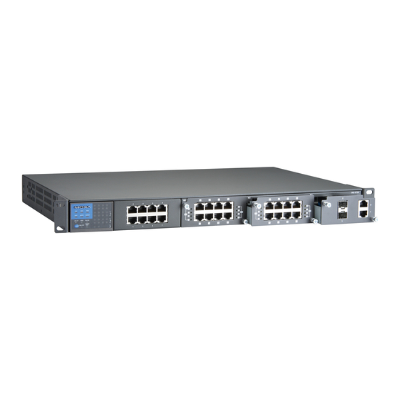
Physical Appearance
Panel Layouts
1. System status LEDs
2. Mode LEDs for the interface module
3. Port LEDs for the interface module
4. Push-button switch for selecting the mode of the interface
module
5. Model name
6. 10/100BaseT(X) port
7. 10/100BaseT(X) PoE port
8. Fast Ethernet / PoE interface module
9. Gigabit Ethernet interface module
10. Serial console port
11. 10-pin terminal block for power inputs and relay output
12. Rack mounting brackets
P/N: 1802067260022
– 1 –
RSPSupply - 1-888-532-2706 - www.RSPSupply.com
http://www.RSPSupply.com/p-9021-Moxa-IKS-6726-8PoE-F-48-T-Managed-Switch.aspx
Dimensions (unit=mm)
Fast Ethernet, PoE Interface Modules (for slot 1)
Gigabit Ethernet Interface Modules (for slot 2)
Rack Mounting
Use four screws to attach the
switch to a standard rack.
– 2 –
Wiring Requirements
WARNING
Be sure to disconnect the power cord before installing
and/or wiring your Moxa industrial rackmount switch.
Calculate the maximum possible current in each power wire
and common wire. Observe all electrical codes dictating the
maximum current allowable for each wire size.
If the current goes above the maximum ratings, the wiring
could overheat, causing serious damage to your
equipment.
Grounding the Rackmount Switch
Grounding and wire routing help limit the effects of noise due to
electromagnetic interference (EMI). Run the ground connection
from the ground screw to the grounding surface prior to connecting
devices.
Wiring the Power Inputs
The IKS series switches support dual redundant power supplies:
Power Supply 1 (PWR1) and Power Supply 2 (PWR2). The
connections for PWR1, PWR2, and the RELAY are located on the
terminal block. The front view of the terminal block connectors is
shown below.
Wiring the Relay Contact
Each IKS switch has one relay
output. Refer to the next section
for detailed instructions on how
to connect the wires to the
terminal block connector, and how to attach the terminal block
connector to the terminal block receptor.
FAULT: The relay contacts of the 10-pin terminal block connector
are used to detect user-configured events. The two wires attached
to the RELAY contacts form an open circuit when a user-configured
event is triggered. If a user-configured event does not occur, the
RELAY circuit will be closed.
Wiring the Redundant Power Inputs
Each IKS switch has two sets of
power inputs: power input 1 and
power input 2.
STEP 1: Insert the dual set positive/negative DC wires into PWR1
and PWR2 terminals (+ pins 1, 9; - pins 2, 10), or insert the
L/N AC wires into PWR1 and PWR2 terminals (L pin 1, 9; N pin
2,10).
STEP 2: Use a screwdriver to tighten the wire-clamp screws on the
front of the terminal block connector.
– 3 –
Advertisement

Subscribe to Our Youtube Channel
Related Manuals for Moxa Technologies IKS-6726-8PoE Series


Summary of Contents for Moxa Technologies IKS-6726-8PoE Series
- Page 1 Package Checklist If the current goes above the maximum ratings, the wiring The Moxa IKS-6726-8PoE series industrial rackmount switches are could overheat, causing serious damage to your shipped with the following items. If any of these items are missing equipment.
- Page 2 Power The corresponding module port’s data is being LED Indicators 48 VDC (44 to 57V) or 110/220 VDC/VAC (88 to Blinking transmitted at Input Voltage 300 VDC, 85 to 264 VAC) System LEDs 1000 Mbps. Max. 1.5/0.75 A @ 110/220 VDC (with 8 fully STAT FDX/HDX loaded PoE ports)
Need help?
Do you have a question about the IKS-6726-8PoE Series and is the answer not in the manual?
Questions and answers