Advertisement
Quick Links
IKS-G6524/G6824 Series
Hardware Installation Guide
First Edition, May 2011
Package Checklist
The Moxa IKS-G6524/G6824 Series industrial rackmount switches
are shipped with the following items. If any of these items are
missing or damaged, please contact your customer service
representative for assistance.
•
IKS-G6524/G6824 switch
•
RJ45 to DB9 console port cable
•
2 power cords
•
Protective caps for unused ports
•
2 rackmount ears
•
Documentation and software CD
•
Hardware installation guide (printed)
•
Warranty card
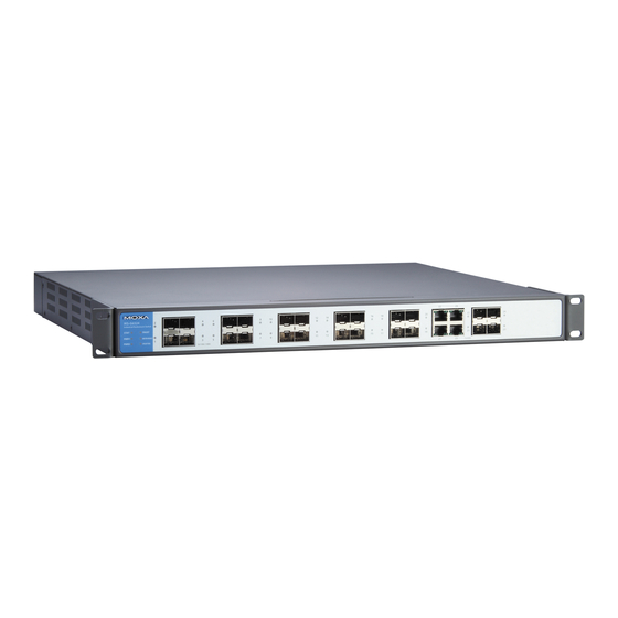
Panel Layouts
1. Model Name
2. System status LEDs
3. 10/100/1000 BaseT(X) port status LEDs
4. 100/1000Base SFP port status LEDs
5. 10/100/1000 BaseT(X) port
6. 100/1000Base SFP slot
7. 10/100/1000 BaseT(X) or 100/1000Base SFP slot combo ports
8. Serial Console port
9. Terminal block for Relay Output, Digital Input
10. AC power sockets for power inputs
11. Grounding screw
– 1 –
Dimensions (unit = mm)
Grounding the Moxa Industrial Rackmount
Switch
Grounding and wire routing help limit the effects of noise due to
electromagnetic interference (EMI). Run the ground connection
from the ground screw to the grounding surface prior to connecting
devices.
Connecting the Power Inputs
The IKS-G6524/G6824 series of switches supports dual redundant
power supplies: Power Supply 1 (PWR1) and Power Supply 2
(PWR2). The connections for PWR1 and PWR2 are located on the
rear side (shown below). Be sure to use a standard power cord
with an IEC C13 connector, which is compatible with the AC power
inlet.
LED Indicators
The front panel of the IKS-G6524/G6824 Series switch contains
several LED indicators. The function of each LED is described in the
table below.
P/N: 1802068240010
– 2 –
LED
Color
State
Description
System LEDs
STAT
GREEN
On
System has passed
self-diagnosis test on
boot-up and is ready to run.
Blinking
System is undergoing the
self-diagnosis test.
RED
On
System failed self-diagnosis
on boot-up.
PWR1
AMBER
On
Power is being supplied to
the main module's power
input PWR1.
Off
Power is not being supplied
to the main module's power
input PWR1.
PWR2
AMBER
On
Power is being supplied to
the main module's power
input PWR2.
Off
Power is not being supplied
to the main module's power
input PWR2.
FAULT
RED
On
System is in the event of
failure, or is under quick
inspection.
Off
System is in normal
operation.
MSTR/
GREEN
On
When the IKS-G6524/G6824
HEAD
is set as the Master of the
Turbo Ring, or as the Head of
the Turbo Chain.
Blinking
The IKS-G6524/G6824 has
become the Ring Master of
the Turbo Ring, or the Head
of the Turbo Chain, after the
Turbo Ring or the Turbo
Chain is down.
Off
The IKS-G6524/G6824 is not
the Master of this Turbo Ring
or is set as a Member of the
Turbo Chain
CPLR/
GREEN
On
When the IKS-G6524/G6824
TAIL
coupling function is enabled
to form a back-up path, or
when it's set as the Tail of
the Turbo Chain.
Blinking
When the Turbo Chain is
down
Off
When this
IKS-G6524/G6824 switch
disables the coupling
function.
– 3 –
Advertisement

Related Manuals for Moxa Technologies IKS-G6524 Series


Summary of Contents for Moxa Technologies IKS-G6524 Series
- Page 1 Color State Description Dimensions (unit = mm) System LEDs STAT GREEN System has passed IKS-G6524/G6824 Series self-diagnosis test on boot-up and is ready to run. Hardware Installation Guide Blinking System is undergoing the self-diagnosis test. First Edition, May 2011 System failed self-diagnosis on boot-up.
- Page 2 effect that overloading of the circuits might have on Color State Description Interface overcurrent protection and supply wiring. Appropriate Port Status LEDs Gigabit Ethernet 10/100/1000BaseT(X) or 100/1000BaseSFP slot consideration of equipment nameplate ratings should be used Console Port RS-232 (RJ45 connector) 10/100/ GREEN The corresponding port’s...
Need help?
Do you have a question about the IKS-G6524 Series and is the answer not in the manual?
Questions and answers