Table of Contents
Advertisement
Quick Links
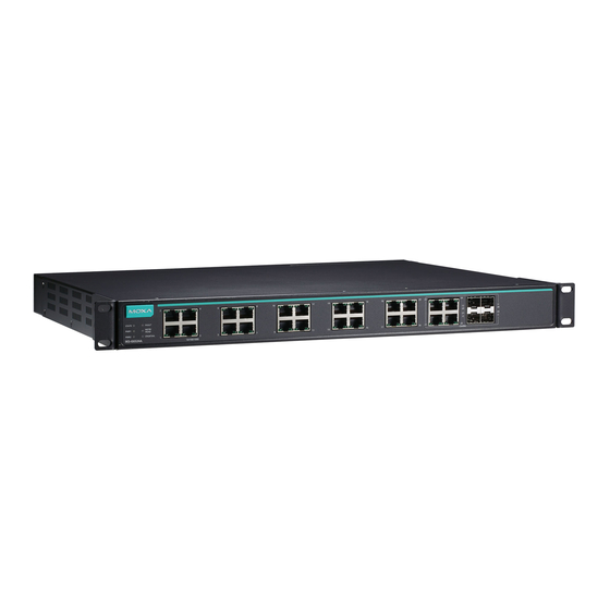
IKS-G6524A/G6824A Series
Quick Installation Guide
Moxa Americas:
Toll-free: 1-888-669-2872
Tel:
1-714-528-6777
Fax:
1-714-528-6778
Moxa Europe:
Tel:
+49-89-3 70 03 99-0
Fax:
+49-89-3 70 03 99-99
Moxa India:
Tel:
+91-80-4172-9088
Fax:
+91-80-4132-1045
Version 3.3, March 2020
Technical Support Contact Information
www.moxa.com/support
2020 Moxa Inc. All rights reserved.
Moxa China (Shanghai office):
Toll-free: 800-820-5036
Tel:
+86-21-5258-9955
Fax:
+86-21-5258-5505
Moxa Asia-Pacific:
Tel:
+886-2-8919-1230
Fax:
+886-2-8919-1231
P/N: 1802065240025
*1802065240025*
Advertisement
Table of Contents

Related Manuals for Moxa Technologies IKS-G6524A Series


Summary of Contents for Moxa Technologies IKS-G6524A Series
- Page 1 IKS-G6524A/G6824A Series Quick Installation Guide Version 3.3, March 2020 Technical Support Contact Information www.moxa.com/support Moxa Americas: Moxa China (Shanghai office): Toll-free: 1-888-669-2872 Toll-free: 800-820-5036 Tel: 1-714-528-6777 Tel: +86-21-5258-9955 Fax: 1-714-528-6778 Fax: +86-21-5258-5505 Moxa Europe: Moxa Asia-Pacific: Tel: +49-89-3 70 03 99-0 Tel: +886-2-8919-1230 Fax:...
-
Page 2: Package Checklist
Package Checklist The Moxa IKS-G6524A/G6824A Series industrial rackmount switches are shipped with the following items. If any of these items are missing or damaged, please contact your customer service representative for assistance. • IKS-G6524A/G6824A switch • USB cable (Type A male to Type B male) •... -
Page 3: Dimensions (Unit = Mm)
Dimensions (unit = mm) Grounding the Industrial Rackmount Switch Grounding and wire routing help limit the effects of noise due to electromagnetic interference (EMI). Run the ground connection from the ground screw to the grounding surface prior to connecting devices. Connecting the Power Inputs The IKS-G6524A/G6824A series of switches supports dual redundant power supplies: Power Supply 1 (PWR1) and Power Supply 2 (PWR2). -
Page 4: Usb Console Connection
USB Console Connection The IKS-G6524A/G6824A series has one USB console port (type B connector), located on the top panel. Use the USB cable (provided in the product package) to connect the IKS-G6524A/G6824A’s console port to your PC’s USB port and install the USB driver (available in the software CD) on the PC. -
Page 5: Led Indicators
LED Indicators The front panel of the IKS-G6524A/G6824A Series switch contains several LED indicators. The function of each LED is described in the following table. Color State Description System LEDs The system has passed the self-diagnosis test on boot-up and is ready to run. -
Page 6: Specifications
Color State Description Port Status LEDs The corresponding port’s link is active. 10/100/1000M GREEN Blinking Data is being transmitted. (TP ports) The corresponding port’s link is inactive. The corresponding port's link is active at 1000 Mbps. Data is being transmitted at 1000 GREEN Blinking Mbps. - Page 7 Interface Gigabit Ethernet 10/100/1000BaseT(X) or 100/1000BaseSFP slot Console Port USB-serial console (Type B connector) Storage Port USB storage (Type A connector for ABC-02-USB) LED Indicators STATE, PWR1, PWR2, FAULT, MSTR/HEAD, CPLR/TAIL Alarm Contact 1 relay output with current carrying capacity of 2 A @ 30 VDC Digital Inputs 1 input with the same ground, but electrically...
-
Page 8: Rack Mounting Instructions
Rack Mounting Instructions 1. Elevated Operating Ambient: If installed in a closed or multi-unit rack assembly, the operating ambient temperature of the rack environment may be greater than room ambient. Therefore, consideration should be given to installing the equipment in an environment compatible with the maximum ambient temperature (Tma) specified by the manufacturer. - Page 9 ATTENTION 1. This device is only for indoor use and Pollution degree 2. 2. Conductors rated to withstand at least 105°C must be used for the Power Supply Terminal. 3. When wiring the relay contact, digital input and power inputs, we suggest using the cable type - AWG (American Wire Gauge) 16-24 and the corresponding pin type cable terminals.
Need help?
Do you have a question about the IKS-G6524A Series and is the answer not in the manual?
Questions and answers