Table of Contents

Related Manuals for Moxa Technologies ICS-G7828A-T Series


Summary of Contents for Moxa Technologies ICS-G7828A-T Series
- Page 1 ICS-G7526A/G7528A/ G7826A/G7828A-T Series Quick Installation Guide Version 1.1, January 2021 Technical Support Contact Information www.moxa.com/support 2021 Moxa Inc. All rights reserved. P/N: 1802075261013 *1802075261013*...
- Page 2 Package Checklist The Moxa ICS-G7526A/G7528A/G7826A/G7828A Series industrial rackmount switches are shipped with the following items. If any of these items are missing or damaged, please contact your customer service representative for assistance. • ICS-G7526A/G7528A/G7826A/G7828A switch • USB cable (Type A male to Type B male) •...
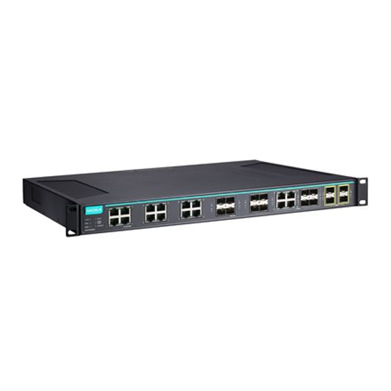
- Page 3 1. Model Name 2. System status LEDs 3. 10/100/1000 BaseT(X) port status LEDs 4. 100/1000 Base SFP port status LEDs 5. 10/100/1000 BaseT(X) port 6. 100/1000 Base SFP slot 7. 10/100/1000 BaseT(X) or 100/1000 Base SFP slot combo ports 8. 10 Gigabit Ethernet SFP+ slot 9.
- Page 4 Wiring the Relay Contact Each ICS-G7526A/G7528A/G7826A/G7828A switch has one relay output. FAULT: The relay contact of the 4-pin terminal block connector is used to detect user-configured events. The two wires attached to the fault contacts form an open circuit when a user-configured event is triggered. If a user-configured event does not occur, the fault circuit remains closed.
- Page 5 LED until it begins blinking more rapidly; this indicates that the button has been depressed for five seconds and you can release the Reset button to load factory default settings. NOTE DO NOT power off the switch when loading default settings. LED Indicators The front panel of the ICS-G7526A/G7528A/G7826A/G7828A switches contain several LED indicators.
- Page 6 Color State Description Port Status LEDs The corresponding port’s link is active. 10/100/ Blinking Data is being transmitted. 1000M GREEN (TP ports) The corresponding port’s link is inactive. The corresponding port's link is active at 1000 Mbps. GREEN Blinking Data is being transmitted at 1000 Mbps. 100/1000M The corresponding port’s link is inactive.
- Page 7 LED Indicators STATE, PWR1, PWR2, FAULT, MSTR/HEAD, CPLR/TAIL Alarm Contact 1 relay output with current carrying capacity of 2 A @ 30 VDC Digital Inputs 1 input with the same ground, but electrically isolated from the electronics. • +13 to +30V for state “1” •...
- Page 8 3. Mechanical Loading: Mounting of the equipment in the rack should be such that a hazardous condition is not achieved due to uneven mechanical loading. 4. Circuit Overloading: Consideration should be given to the connection of the equipment to the supply circuit and the effect that overloading of the circuits might have on overcurrent protection and supply wiring.
Need help?
Do you have a question about the ICS-G7828A-T Series and is the answer not in the manual?
Questions and answers