
Related Manuals for Carrier 30WI


Summary of Contents for Carrier 30WI
- Page 1 C O N T R O L S M A N U A L Chiller - Heat Pump Control 30WI Translation of the original document...
-
Page 2: Table Of Contents
CONTENTS 1 - IMPORTANT RECOMMENDATIONS ............................5 1.1 - Electrical power supply................................5 1.2 - Board controller specifications ..............................5 1.3 - Warning ..................................... 5 1.4 - Earthing ..................................... 5 1.5 - Connection of sensors................................5 1.6 - Connection of communication buses and of the remote console ....................5 1.7 - Connection of on/off inputs .................................. - Page 3 CONTENTS 13 - MANAGEMENT OF THE FUNCTIONS ............................. 73 13.1 - Management of the compressor protections ......................... 73 13.2 - Management of the time counters ............................73 13.3 - Management of compressor start-up ............................ 73 13.4 - Compressor stopping sequence :............................74 13.5 - Management of the reversing valves ............................
- Page 4 CONTENTS 27 - MANAGEMENT OF A REFRIGERANT FLUID LEAK AND LEAK FAULT DETECTOR ............116 27.1 - Link between the CAREL detector and the controller : ....................... 116 27.2 - Management of faults when a leak is detected by the CAREL unit if P104 = YES : ............116 27.3 - Management of faults if communication (bus) with the CAREL unit is lost if P104 = YES ..........
-
Page 5: Important Recommendations
1 - IMPORTANT RECOMMENDATIONS 1.6 - Connection of communication buses and Your unit is equipped with a microprocessor-controlled electronic of the remote console circuit board. To ensure the correct operation of your machine, you must follow the rules listed below. 1.6.1 - Connection cable specifications 1.1 - Electrical power supply - Flexible cable –... -
Page 6: General
2 - GENERAL This controller is fitted as standard on water chillers (or water heaters) equipped with one or two refrigerating circuits and scroll compressors. It is fitted on water-to-water, air-to-water and reversible air-to-water units. Depending on the configuration, the board provides the following functions: - Control of chilled water or hot water temperatures. - Continuous monitoring of operating parameters. - Diagnostics and fault storage. -
Page 7: Composition
3 - COMPOSITION The controller consists of: - One control and display panel fitted on the unit. - One non-reversible circuit = one main board. - One reversible circuit = one main board + one additional board (No. 1) → rotary switch in position 1. - Two non-reversible circuits = one main board + one additional board (No. 2) two circuits → Rotary switch in position 1. - Two reversible circuits = one main board + one additional board (No. 2) two circuits → Rotary switch in position 1. + one additional board (No. 2), two circuit changeover → Rotary switch in position 2. - One auxiliary electric heater control board = additional board 1 → Rotary switch in position 2 (optional, ILD range). - One remote console (optional). - One relay board for operating states and faults (optional). 3.1 - Main control board for machines with one non-reversible refrigerating circuit 3 2 1 3 2 1... -
Page 8: Additional Board 1
3 - COMPOSITION TERMINAL BLOCK J8 (analogue inputs) 3.2.2 - Rotary switch set to position 2 - Use of 1-2 Refrigerant temperature sensor, circuit 1 electric auxiliary heaters 2-3 10 K suction temperature sensor, circuit 1 4-5 10 K liquid temperature sensor, circuit 1 TERMINAL BLOCK J1 6-7 50 K discharge temperature sensor, stage 1, circuit 1 Flash Memory connector... - Page 9 3 - COMPOSITION TERMINAL BLOCK J5 (analogue inputs) 3.3.2 - Rotary switch set to position 2 - Two circuit reversal use 1 Common 2 Available TERMINAL BLOCK J1 3 +5 V power supply for pressure sensors Flash Memory connector 4 0-5 V input for HP sensor on circuit 2 TERMINAL BLOCK J2 (on/off inputs) 5 0-5 V input for LP sensor on circuit 2 1-2 Heating/cooling selection input if unit type (P2) = reversible...
-
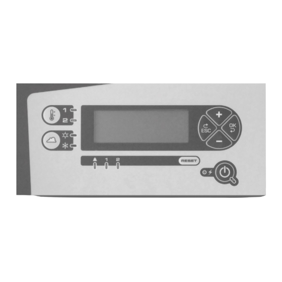
Page 10: Control And Display Console
3 - COMPOSITION 3.4 - Control and display console Confirm button Setpoint 1/ Cancel Setpoint 2 button button Heating/ Cooling selection On/Off button button General fault LED Reset Power LED Circuit fault LED The local console and the remote control console have the same front. Mounting dimensions (in mm) of remote control console Ø... -
Page 11: Connection Via Rs485 Serial Port For Cms Or Control Console And Multi Controller Unit
3 - COMPOSITION 3.5 - Connection via RS485 serial port for CMS or control console and Multi controller unit CHILLER/ HEAT PUMP MULTI GROUP CONTROL main board main board Unit 2 Shield To additional board A B 0V A B 0V 1 2 3 4 Shield Remote control console... -
Page 12: Description
4 - DESCRIPTION 4.1 - Main board 4.3 - Man-Machine Communication Main board for units with one non-reversible refrigerating circuit: ■ Local console: - The controls on the local console are enabled regardless of ■ Analogue inputs: the value of P103. - Acquire signals measured by temperature sensors. -
Page 13: Access Levels
5 - ACCESS LEVELS The CHILLER/HEAT PUMP controller features three parameter access levels: - Level 1: Users - Level 2: Technicians/Maintenance - Level 3: Manufacturer’s technicians (full access) 5.1 - Selecting an authorised access level Authorised access levels are selected in menu 14 (ACC. LEVEL SELECT.). The following screen appears: C O N T R O L L E R L E V E L 1 4 - 1... -
Page 14: Configuring Access Levels On The Controller
5 - ACCESS LEVELS 5.2.3 - Access to level 3 A non-modifiable numeric code must be entered to access level 3: - The following menu for entering this code appears when LEVEL 3 is selected: L E V E L A C C E S S C O D E * * * * - Using the + and - buttons, replace this first symbol (*) by the first character in the code and press Enter. -
Page 15: Classification Of The Menus And Their Functions
5 - ACCESS LEVELS 5.5 - Classification of the menus and their functions ■ Level 1: ► Menu : Setpoint, machine status, measured values, control parameters, operation parameters, fault memory, hourly scheduling, communication and access level selection. ► Fonction : All functions accessible via the console: On/Off, Reset, Heating/Cooling selection;... -
Page 16: List Of Parameters
6 - LIST OF PARAMETERS 1 = Access to USER parameters (level 1 parameters only) ACCESS LEVEL : 2 = Access to visible and editable parameters (level 1 and 2 parameters). EDITABLE numeric code. 3 = Access to Manufacturer’s parameters (level 1, 2 and 3 parameters). UNEDITABLE numeric code technician No. - Page 17 6 - LIST OF PARAMETERS No. Description Setting Default Display conditions Option Breakdown (continued) 45 with R410A 36 High pressure, LP 1 sensor 10 to 50 b (resolution: 0,1) 17,3 b if P42 = VCM -0,5 37 Low pressure, LP 1 sensor -1 to 10 b (resolution: 0,1) 0 with R410A 45 with R410A...
- Page 18 6 - LIST OF PARAMETERS No. Description Setting Default Display conditions Configuration Client 100 Language F - GB - D - SP - I 101 Date DAy/MOnth/YEar 102 Hour HOurs/MInutes 103 Control type Local - remote (BMS) Local 104 Leak detection Yes - No 2 104,1 Leak detection time delay 0 to 5 min...
- Page 19 6 - LIST OF PARAMETERS No. Description Setting Default Display conditions Control 1- Return 141 Control mode 3- Water supply 4- Supply with compensation Visible if P2 = 1 and P141 = 1 and heating mode 142 Water loop winter protection No - Yes Visible if P2 = 1 and cooling mode Visible if P2 = 2 or 3...
- Page 20 6 - LIST OF PARAMETERS Description Setting Default Display conditions High Pressure Control If P1 = R410A and P2 = 2, 3 or 4 and 191 Low Noise operation Yes - No P180 = 1 - If P7 ≠ Inverter and P10 = Pressure 192 Max. fan speed threshold 5 to 10 V 5,6 V if P7 = (P21 = 2 or 3, P180 = 1 and hidden)
- Page 21 6 - LIST OF PARAMETERS Description Setting Default Display conditions Read-only (continued) 268 Value of reference ΔT for defrosting of circuit 1 If P159 = Optimised 269 Value of reference ΔT for defrosting of circuit 2 If P159 = Optimised and P3 = 2 270 Controller action time delay 271 DHP on differential If P2 = 3 273,1 Supply voltage If P15,1 = Yes 274,1 Machine current input...
- Page 22 6 - LIST OF PARAMETERS Description Setting Default Display conditions Circuit 2 (continued) 333,2 Desuperheat on discharge 4 P332,2 - P331 If P3 = 2 and P5 = 2 334 Circuit 2 LP If P3 = 2 335 Circuit 2 evaporation temperature See appendix If P3 = 2 336 Circuit 2 suction temperature...
- Page 23 6 - LIST OF PARAMETERS Description Setting Default Display conditions Outputs (continued) 437 State of recovery heat trace cable control output On/Off If P2 ≠ 1 (water-to-water) and P29,1 = Yes 438 State of maximum power output On/Off If P111 = Max. power 439 State of boiler output On/Off If P111 = Boiler 440 State of cooling/heating output...
- Page 24 6 - LIST OF PARAMETERS Description Setting Default Display conditions Circuit 2 (continued) If P42 = VCM and P3 = 2 616 Opening of C2 valve when heat pump started 10 to 100 % and P2 = reversible air-to-water 617 Opening time at start-up, C2 1 to 60 seconds If P42 = VCM and P3 = 2 618 Circuit 2 slow mode...
-
Page 25: Management Of The Drycooler Controller Parameters
7 - MANAGEMENT OF THE DRYCOOLER CONTROLLER PARAMETERS Setting parameter P116 (Drycooler link) to “Yes” provides access to all Drycooler controller parameters in read/write mode only if a bus connection has been created between the two items of equipment 1 3 - D R Y C O O L E R - Menu 13 allows all information about the Drycooler controller to be displayed on the heat pump or chiller console without having the console mounted on the Drycooler. -
Page 26: Contents Of The Menus
8 - CONTENTS OF THE MENUS The ° symbol stands for °C in the electronic programming system. Analogue values are displayed with one decimal place. The hundreds digit may be replaced by a negative sign when appropriate. A selection symbol flashes at the left of the display. Holding down the + or - buttons will cause increasingly faster scrolling (and change the units) in the list of parameters or when modifying parameter values. - Page 27 8 - CONTENTS OF THE MENUS 8.3.1 - Main table This screen reappears automatically after one hour if No general faults occur, no controls are activated (via the console, modem, etc.), no general faults are reported and no automatic controls are closed: D D / M M / Y Y h h / m m R E T U R N...
- Page 28 8 - CONTENTS OF THE MENUS 8.3.2 - MACHINE STATUS table This table appears only if any of the following messages must be displayed using the ↑and ↓ buttons. The messages are displayed in the following order of priority: M A C H I N E S T A T U S F A N F A U L T P U M P X X S P U M P...
- Page 29 8 - CONTENTS OF THE MENUS C I R C R E F F R O S T E F A U L T C U T ( S ) 2 4 H C I R C U I T B R E A K F A U L T F A U L T...
- Page 30 8 - CONTENTS OF THE MENUS S U C T I O N T E M P . S E N S O R F A U L T C I R C . x J x / x x - x x E X C H .
-
Page 31: Measured Values Menu
8 - CONTENTS OF THE MENUS 8.3.4 - Electric stages table: E L E C . S T A G E S S H U T O F F L O A D S H E D D I N G I N P U T E L E C . -
Page 32: Machine Parameters Menu
8 - CONTENTS OF THE MENUS 8.5 - MACHINE PARAMETERS menu To access the MACHINE PARAMETERS menu, use the + or - buttons to position the cursor on 4 then press OK. The display shows the list of configuration parameters. Use the + and - buttons to scroll through the tables at a rate of two rows at a time. To modify a parameter the configuration must be unlocked (via parameter P99). This turns off the machine. ■... - Page 33 8 - CONTENTS OF THE MENUS Number of evaporators: P O 6 N O . E V A P O R A T O R S P 0 6 N O . E V A P O R A T O R S Compressor suppliers: P 0 7 C O M P R E S S O R...
- Page 34 8 - CONTENTS OF THE MENUS Tandem type: P 1 3 B A L A N C E D T A N D E M C O M P R E S S O R Y E S P 1 3 B A L A N C E D T A N D E M C O M P R E S S O R...
- Page 35 8 - CONTENTS OF THE MENUS Pump controlled by operation of boiler: P 2 7 P U M P C O N T R O L L E D B O I L E R P 2 7 P U M P C O N T R O L L E D B O I L E R Y E S...
-
Page 36: Adjustment Parameters Menu
8 - CONTENTS OF THE MENUS LP fault threshold: P 5 5 F A U L T T H R E S H O L D x x . x b LP slope factor: P 5 8 S L O P E F A C T O R x . - Page 37 8 - CONTENTS OF THE MENUS Control type: P 1 0 3 C O N T R O L T Y P E L O C A L P 1 0 3 C O N T R O L T Y P E R E M O T E ( B M S , e t s .
- Page 38 8 - CONTENTS OF THE MENUS Mode de fonctionnement : P 1 1 9 O P E R A T I O N C O O L I N G P 1 1 9 O P E R A T I O N H E A T I N G P 1 1 9 O P E R A T I O N...
- Page 39 8 - CONTENTS OF THE MENUS Maximum setpoint at end of drift in cooling mode: P 1 3 0 M A X S T P D R I F T E N D C O O L I N G x x °...
- Page 40 8 - CONTENTS OF THE MENUS Time coefficient: P 1 4 8 C O E F F I C I E N T x x x s Control with compensation: P 1 5 0 C O M P E N S A T I O N C O E F F I C I E N T x .
- Page 41 8 - CONTENTS OF THE MENUS Charge limit function: P 1 7 1 M A X W A T E R T E M P . S T A G E L O A D S H E D - x x , x ° Load shedding via ON/OFF input: P 1 7 5 T Y P E...
- Page 42 8 - CONTENTS OF THE MENUS Outdoor temperature at which the heating elements are turned on: P 2 2 0 O U T . T E M P E R A T U R E W I N T E R P R O T E C .
- Page 43 8 - CONTENTS OF THE MENUS P 6 0 3 C I R C U I T M O P P O I N T Y E S P 6 0 4 C I R C U I T M O P V A L U E 1 5 °...
-
Page 44: Operation Parameters Menu
8 - CONTENTS OF THE MENUS Number of stop bits: P 7 0 3 N U M B E R S T O P B I T S Format of real numbers: P 7 0 4 S W A P P E D R E A L N U M B E R F O R M A T... - Page 45 8 - CONTENTS OF THE MENUS LED test: used to turn on the console LEDs corresponding to the machine configuration: P 2 5 0 L E D T E S T Control setpoint: P 2 5 1 C O N T R O L S E T P O I N T x x . x ° Outdoor air temperature: P 2 5 2 O U T D O O R...
- Page 46 8 - CONTENTS OF THE MENUS Calculated frosting time, circuit 1: P 2 6 6 C A L C U L A T E D F R O S T . T I M E C I R C U I T x x m n Calculated frosting time, circuit 2: P 2 6 7...
- Page 47 8 - CONTENTS OF THE MENUS Desuperheat temperature on discharge 1 (= discharge temperature – condensation dew point temperature) : P 3 0 3 . 1 D I S C H A R G E D E S U P E R H E A T x x .
- Page 48 8 - CONTENTS OF THE MENUS Number of cut-offs caused by discharge temperature on stage 1 in 24 hours : P 3 2 4 . 1 N O . D I S C H A R G E C U T S 2 4 H Number of cut-offs caused by discharge temperature on stage 2 in 24 hours : P 3 2 4 .
- Page 49 8 - CONTENTS OF THE MENUS Circuit 2 evaporating temperature value resulting from the previous pressure value and the refrigerant selected : P 3 3 5 C I R C U I T E V A P . T E M P . x x x .
- Page 50 8 - CONTENTS OF THE MENUS Percentage of opening for the electronic expansion valve on circuit 2 : P 3 5 5 E X V O P E N I N G X X X % Circuit 2 liquid temperature : P 3 5 6 C I R C U I T L I Q U I D...
- Page 51 8 - CONTENTS OF THE MENUS State of stage 2 override input : P 4 1 5 S T A G E O V E R R I D E I N P U T O P E N State of stage 3 override input : P 4 1 6 S T A G E O V E R R I D E...
- Page 52 8 - CONTENTS OF THE MENUS Heater contact : P 4 3 6 H E A T E R O U T P U T Contact for frost protection heat trace cable (recovery option) : P 4 3 7 R E C O V E R Y F R O S T P R O T .
- Page 53 8 - CONTENTS OF THE MENUS Speed control information (intertwined coil) : P 4 4 7 S T A G E D R I V I N G V O L T A G E X X . X V Speed control information (split or mixed coil), stage 1, circuit 1 : P 4 4 8 S T A G E...
-
Page 54: Fault Memory Menu
8 - CONTENTS OF THE MENUS Machine identification name : P 5 7 2 M A C H I N E L O C A T I O N X X X X X X X X X X X X X X X X X X X X X X Machine identification number : P 5 7 3 M A C H I N E... -
Page 55: Test Mode Menu
8 - CONTENTS OF THE MENUS Reading for saving faults to memory : ■ Reading if a circuit fault occurs: information on circuit that cut off H P X : x x x . x b T C O N D : + x x . x ° ↑... - Page 56 8 - CONTENTS OF THE MENUS a) Start-up procedure - The test function will only be authorised to run if the unit is shut down. - The circuit must be available (no forced shut-down of the 2 compressors; no fault) - The normal HP test can only be performed from the local control console (not from the remote control console or from a CMS).
-
Page 57: Management Of The On/Off Inputs
9 - MANAGEMENT OF THE ON/OFF INPUTS 9.1 - Automatic machine operation control This input is used by the customer. This control allows customers to remotely prevent the machine from operating. - The On/Off LED flashes when this control is on. - Message on display: SHUT OFF BY MACHINE AUTO CONTROL Contact state: closed or connected by a jumper (automatic machine operation control = Yes) 9.2 - Load shedding control The load shedding controls on the main board are used to turn off the stages on circuit 1. -
Page 58: Fan Fault (Circuits 1 And 2)
9 - MANAGEMENT OF THE ON/OFF INPUTS 9.3.2 - Management for water-to-water units in heating mode A time delay is necessary to manage this fault. ■ If ≤ 3 stops in 1 hour This time delay is : ► If a fault occurs : - Determined by P109 if P108 = depending on control mode - Pump 2 is shut off - 10 seconds if P108 = depending on On/Off. -
Page 59: Expansion Valve Fault
9 - MANAGEMENT OF THE ON/OFF INPUTS 9.5 - Expansion valve fault ■ If P42 = ALCO This configuration corresponds to using the electronic expansion valve with the Alco driver module and display. Only fault feedback signals from the valve are managed in this case. The fault signal contact on the electronic expansion valve on circuit 1 must be wired to terminals 5-6 on terminal block J5 on the motherboard. -
Page 60: Phase Controller Fault
9 - MANAGEMENT OF THE ON/OFF INPUTS Expansion valve VCM board fault : C I R C U I T O F F E X P . V A L V E F A U L T F A U L T E X V C U T S 2 4 H... -
Page 61: Compressor Protection
9 - MANAGEMENT OF THE ON/OFF INPUTS B) If a fault occurs on the second pump as well, the unit is shut off and the following message appears M A C H I N E O F F P U M P A N D F A U L T - Saved in fault memory... -
Page 62: Setpoint Selection Via On/Off Input
9 - MANAGEMENT OF THE ON/OFF INPUTS 9.10 - Setpoint selection via on/off input If the number of setpoints = 2 with selection via on/off input (the on/off input corresponds to terminals 4-6 on terminal block J6 on the motherboard). ■... -
Page 63: Operating Mode Selection
9 - MANAGEMENT OF THE ON/OFF INPUTS STP = Setpoint Displayed if P120 = 3 and in cooling mode : P 1 2 5 . 1 S T P F O R 4 m A C O O L I N G - x x , x °... -
Page 64: Management Of The Analogue Inputs
10 - MANAGEMENT OF THE ANALOGUE INPUTS 10.1 - Temperature sensor Diagram of sensors: All sensor faults are taken into account in the fault memory +5 V +5 V R = 8.96 K Ω R = 15.4 K Ω 50 k Ω sensor 10 k Ω sensor ■ Water inlet sensor : CTN 10 K at 25°C (if P2 = 1, 2 or 3) This sensor monitors the water temperature on the exchanger inlet in order to : - Adjust the unit (water return control). - Page 65 10 - MANAGEMENT OF THE ANALOGUE INPUTS ■ Outdoor air sensor: CTN 10 K at 25°C This sensor monitors the temperature of the outdoor air in order to : - Adjust the system based on the outdoor temperature (cooling and heating). If the sensor wire is cut (open circuit) or the sensor short-circuits, the unit is adjusted to the setpoint value (heating and cooling) and a fault is displayed.
- Page 66 10 - MANAGEMENT OF THE ANALOGUE INPUTS ■ Heat exchanger ambient sensor : CTN 10 K at 25°C (if P2 = 2) This sensor monitors the temperature inside the hydraulic enclosure housing the heat exchanger(s) in order to: - Turn on the heaters - Display the temperature inside the enclosure (display range: 40 to 99.9°C, resolution: 0.1 K) - Automatic acknowledgement E X C H A N G E R A M B I E N T T E M P .
-
Page 67: Pressure Sensor
10 - MANAGEMENT OF THE ANALOGUE INPUTS ■ Correspondence table : SENSOR RESISTANCE Ω Temperature (°C) DISCHARGE SENSOR CONTROL AND OUTDOOR 50 KΩ SENSOR 10 KΩ 55340 42340 162250 32660 126977 25400 99517 19900 78570 15710 62468 12490 50000 10000 40280 8058 32650... - Page 68 10 - MANAGEMENT OF THE ANALOGUE INPUTS When reading the operation parameters for the pressure levels while the machine is on, the sensors can be adjusted with the OK button if there is a difference between a value that is read and the corresponding value measured by a pressure gauge. Exemple : P 3 x x H P x P R E S S U R E...
-
Page 69: Management Of The Water Pumps
11 - MANAGEMENT OF THE WATER PUMPS 11.1 - Pump 1 Pump 1 is assigned to the main hydraulic network. Therefore, it is used in all configurations: - If P2 = air-to-water or reversible air-to-water and P25 = 2, it will be managed alternately with Pump 2. The pump that has run for the shortest amount of time starts up first. - Otherwise, the pumps may be turned on using the On/Off button (and automatic operation control input closed). The pump is shut off 1 minute after the last control stage turns off. -
Page 70: Actuation Of Variable-Speed Pump 1 On Water-To-Water Machines Via The 0/10V Output
11 - MANAGEMENT OF THE WATER PUMPS 11.5 - Actuation of variable-speed pump 1 on water-to-water machines via the 0/10V output: Addition of functions necessary for actuation of pump 1 (indoor network), not supplied, in variable speed mode using a 0/10V output with a PID algorithm. - Page 71 11 - MANAGEMENT OF THE WATER PUMPS P240.6: Pump 1, boost mode max. speed P 2 4 0 . 6 M A X S P E E D B O O S T M O D E P U M P 1 0 0 % P240.7: Pump 1, STANDARD mode min.
-
Page 72: Winter Protection
12 - WINTER PROTECTION 12.1 - Frost protection of pumps and heat exchangers while unit is off This function protects the pump(s) and the heat exchanger(s) from freezing. The heater and heat trace cable outputs are enabled only when P2 = air-to-water and reversible air-to-water. P265 becomes visible if P2 = air-to-water and reversible air-to-water 12.1.1 - Use with pure water: If P52 ≥... -
Page 73: Management Of The Functions
13 - MANAGEMENT OF THE FUNCTIONS 13.1 - Management of the compressor protections 13.1.1 - Short-cycle protection : Information from compressor manufacturer: Compressors are not allowed to start more than 12 times an hour (on/off time of 5 minutes and minimum of 3 minutes between starts). The on time + off time will be adjustable via parameter P50. -
Page 74: Compressor Stopping Sequence
13 - MANAGEMENT OF THE FUNCTIONS 13.3.1 - With balanced tandem compressors : Before stages are turned on, the runtime of each stage is always checked so that the stage that has run the least is started first. When only one of the two compressors on each circuit is running, it is turned off after 4 hours and the other compressor is turned on. ►... -
Page 75: Management Of The Reversing Valves
13 - MANAGEMENT OF THE FUNCTIONS 13.5 - Management of the reversing valves The reversing valves are fitted on reversible units only. They are managed by the following convention: - In cooling mode: the reversing valves are supplied. - In heating mode: the reversing valve are not supplied. The supply to the reversing valves is cut off 30 minutes after the last stage on the corresponding circuit is turned off. -
Page 76: Self-Adjusting Functions
14 - SELF-ADJUSTING FUNCTIONS These functions allow the machine to adjust itself to certain occasionally extreme operating conditions and thus avoid stops caused by faults. 14.1 - Self-adjusting function: water frost limit ► Operation : - Before shutting down after a fault occurs, the unit reduces its power by turning off a stage (if there are two on the circuit), or by reducing the compressor to half speed. -
Page 77: Self-Adjusting Function: Discharge Protection, Circuit 1 Or 2
14 - SELF-ADJUSTING FUNCTIONS 14.4 - Self-adjusting function: discharge protection, circuit 1 or 2 ► Operation : - Before shutting down after a circuit fault occurs, the unit reduces its power for 30 minutes by turning off a stage. - The threshold is detected by the discharge sensor at value P51 and the stage that was turned off is returned to normal operation after 30 minutes. -
Page 78: Fault Functions
15 - FAULT FUNCTIONS 15.1 - Water frost limit fault on circuits 1 and 2 ► Operation : - Should the self-adjusting function be insufficient, a fault will occur on the unit when the temperature measured on the heat exchanger water outlet is at P52 (measured for 15 seconds, or P52 – 1 K). ■... -
Page 79: Hp Pressure Fault, Circuits 1 And 2
15 - FAULT FUNCTIONS ■ If this fault causes more than 3 shutdowns in 24 hours : - Corresponding circuit shut off. - Fault output on - Frost protection fault relay on optional board in On position - Circuit fault LED on console lit steady - Boiler on if P111 = Boiler and heating mode. -
Page 80: Lp Fault On Circuit 1 Or 2
15 - FAULT FUNCTIONS ► Display : D . T E M P F A U L T x x m n C U T ( S ) 2 4 H ■ If this fault causes more than 5 shutdowns in 24 hours : - Corresponding circuit shut off. -
Page 81: Management Of Superheat Faults
15 - FAULT FUNCTIONS 15.6 - Management of superheat faults The superheat temperature on the suction end of each circuit can be monitored by comparing the LP saturation temperature to the suction temperature. This protection is enabled by setting P43 to ‘Yes’ (No by default). It protects the compressor(s) from excessively low or high superheat values. -
Page 82: Controls
16 - CONTROLS 16.1 - Main control in cooling and heating modes ■ Definition and principle : The chilled water and hot water temperatures are measured and compared with the setpoint value. Depending on the result, the compressor stages are turned on or off. This check is performed on the heat exchanger’s water outlet (water supply = PIDτ) or water inlet (water return). 16.1.1 - Operating mode selection (P119) : - If P119 = 1 (Cooling) Cooling only. -
Page 83: Water Temperature Setpoint Adjustment
16 - CONTROLS - When an operating mode reaches its end temperature setpoint in automatic mode, the following message is displayed until a mode is turned on : D E A D B A N D A U T O H E A T I N G / C O O L I N G The two heating and cooling LEDs flash while this message is displayed. - Page 84 16 - CONTROLS Exemple : Two-stage water heater for a water temperature range of 35 40°C. Parameter settings: STP = 40°C, SD = 2 K, ISD = 1.5 K. Stage 1 Stage 2 36,5 38,5 Stage 2 Stage 1 Water inlet temp. 36,5 38,5 R E T U R N T E M P . : - x x . x ° S E T P O I N T : - x x .
- Page 85 16 - CONTROLS Example: Two-stage unit with a 45°C setpoint. I = 0 and D = 0. Stage 1 Stage 2 Stage 1 44,5 45,5 44,34 44,66 45,33 45,66 44,5 44,75 45,25 45,9 S U P P L Y T E M P . : - x x . x ° S E T P O I N T : - x x .
-
Page 86: Adjustment Of Setpoint For The Water Supply And Return Temperatures (P141 = 1 Or 2) If P7 = Inverter
16 - CONTROLS Action of controller with Action of controller without compensation compensation P148 Time saved by compensation P151 R = 0 90 s 35 s 7.5 s A: 1 st compensation result. The controller’s remaining time is (100 - 10 = 90 seconds) × 0.5 = 45 seconds. B: 2 nd compensation result. - Page 87 16 - CONTROLS ► In heating mode : - A call will be made to turn on the compressor if T < STP + Stage differential - The compressor rotation speed will be progressively increased if (STP - Stage differential - Interstage differential) < T < (STP - Stage differential) - The compressor will be shut off as soon as T >...
-
Page 88: Storage Control
16 - CONTROLS 16.5 - Storage control If P154 = No → The control mode remains standard and may be adjusted to the return or supply line depending on the value of P141 (control mode). If P154 = Yes → Storage control is enabled. The control mode is managed based on the setpoint selected: - If setpoint 1 is selected, the control remains standard and the mode (supply or return) is selected by P141 (control mode). - If setpoint 2 is selected, the control automatically switches to ‘return with storage’ mode. This type of control makes it possible to generate maximum capacity at a given time, often when electricity is cheapest. -
Page 89: Automated Self-Regulating Control
16 - CONTROLS 16.6.3 - Management of the setpoint based on the outdoor temperature : The water controls in COOLING and heating mode are activated by default (P127 and P131 are set to “Yes” by default). Gradients are managed during operation with two setpoints in the following manner: Depending on the outdoor temperature, the water control with setpoint 2 is parallel to the control set using setpoint 1. -
Page 90: Control Of Condensing Pressure For Air-Cooled Units
17 - CONTROL OF CONDENSING PRESSURE FOR AIR-COOLED UNITS 17.1 - Control during normal operation or on/off control ► In heating mode : All the fan stages are turned on at maximum speed: - Once a compressor stage is running on the unit when P11 = intertwined - Once a compressor stage is running on the circuit when P11 = split. -
Page 91: Forced And Self-Adjusting Control
17 - CONTROL OF CONDENSING PRESSURE FOR AIR-COOLED UNITS C) On/Off, where (P21 = No), P10 = propeller and P11 = intertwined - Control mode is turned on as soon as a compressor stage is running on the unit. - Stages 1 and 2 are controlled by each circuit. - Common stage 1 is turned on as soon as the first control stage for circuits 1 and 2 is turned on. ... - Page 92 17 - CONTROL OF CONDENSING PRESSURE FOR AIR-COOLED UNITS 17.3.1 - Variable speed drive (VSD) : In order for it to adjust the speed based on the 0-10 V signal, the variable speed drive selected must first be supplied electrically and informed of the direction of rotation. ► VSD power supply : Power will be supplied, via the power contactors, by the control for fan 1 on circuit 1 (terminal 5 on terminal block J3), the control for fan 1 on circuit 2 (terminal 6 on terminal block J3 on additional card 2) and the control for fan 1 common to both circuits (terminal 5 on terminal block J3 on additional board 2).
- Page 93 17 - CONTROL OF CONDENSING PRESSURE FOR AIR-COOLED UNITS The minimum value of P181 becomes 16 bar for R410A. The minimum value of P183 becomes 8 bar for R410A. 17.3.3 - Fan speed control with intertwined coils (P11 = intertwined): Speed control mode is turned on as soon as the unit is on.
- Page 94 17 - CONTROL OF CONDENSING PRESSURE FOR AIR-COOLED UNITS If P180 = 3 stages: 15-30% and 70-85% for stages 2-3 If P180 = 2 stages: 20 and 80% for stage 2 The values of P181 and P183 must be set. P181 = 17.8 b for R410A, 12 b for R407C, 11.0 b for R22 and 6.8 b for R134a P183 =7.8 b if R410A or 5.5 b if R407C, 5.0 b if R22 and 3.8 b if R134a In this case parameters P181 and P183 can be adjusted (resolution of 0.1) and parameter P184 becomes needless and therefore inaccessible.
-
Page 95: Low Noise Control (Single-Fan Units Only)
17 - CONTROL OF CONDENSING PRESSURE FOR AIR-COOLED UNITS 17.3.8 - Speed control of electronically commutated pressure fans (P10 = Pressure) : This function provides the same functionalities as the variable speed drive described above with the added possibility of allowing the customer to limit the speed of the fans in order to lower the sound level or best adjust the available pressure. -
Page 96: Total Recovery Control
17 - CONTROL OF CONDENSING PRESSURE FOR AIR-COOLED UNITS 17.5 - Total recovery control The total recovery function and its associated parameters (P29 and P193) are accessible only if P2 = air-to-water: P 2 9 T O T A L R E C O V E R Y - P193 visible If P29 = Yes P 1 9 3... - Page 97 17 - CONTROL OF CONDENSING PRESSURE FOR AIR-COOLED UNITS One-circuit unit (or fault on one circuit of a two-circuit unit) : Adjust as shown in diagram 1. Two-circuit unit and if the compressor on circuit 2 running for at least 5 seconds : - If HP1 or HP2 < A → Control shown in diagram 1 and taking into account the sensor with the lowest pressure.
-
Page 98: Control Of Condensing Pressure For Water-To-Water Units
18 - CONTROL OF CONDENSING PRESSURE FOR WATER-TO-WATER UNITS 18.1 - Operation with a two-way valve If municipal wastewater is used to cool the condenser, we recommend installing the two-way valve so as to be able to set the condensing pressure to a value that will ensure correct operation of the unit and save on cooling water. -
Page 99: Restriction Of Operation Of The Machines Based On The Outdoor Temperature
19 - RESTRICTION OF OPERATION OF THE MACHINES BASED ON THE OUTDOOR TEMPERATURE 19.1 - Restriction to the minimum air temperature in heating mode P 2 2 5 M I N . A I R T E M P . H E A T I N G M O D E - x x °... -
Page 100: Restriction To The Maximum Air Temperature In Heating Mode
19 - RESTRICTION OF OPERATION OF THE MACHINES BASED ON THE OUTDOOR TEMPERATURE ► If a fault occurs : - Fault stored in memory in case of a mains power failure - Fault saved in fault memory - Relay in On position - Unit fault LED lit steady. -
Page 101: Management Of The Auxiliary Heater Board And The Electric Auxiliary Heaters
20 - MANAGEMENT OF THE AUXILIARY HEATER BOARD AND THE ELECTRIC AUXILIARY HEATERS The auxiliary electric heater board is the additional board 1 with Inputs the rotary switch in position 2. It is used to obtain up to four additional control stages in heating mode. - Page 102 20 - MANAGEMENT OF THE AUXILIARY HEATER BOARD AND THE ELECTRIC AUXILIARY HEATERS Management of the electric auxiliary heaters when the thermodynamic control stage is shut off by a setpoint corrected by the discharge protection : - The electric stages take the place of the thermodynamic stages and become the first control stages, and the outdoor air temperature at that exact moment is stored in memory. - The auxiliary heaters are set to the initial setpoint if P131 (setpoint adjustment based on outdoor temperature) = No.
-
Page 103: Management Of The Back-Up Boiler
21 - MANAGEMENT OF THE BACK-UP BOILER ■ If P111 = Boiler ► Management under normal operation : Setpoint P134 Setpoint = f (Text) in °C Boilers only Heat pump and boiler Heat pump only P225 P226 Outdoor air temperature (°C) - If the air temperature ≥ P226: heat pump alone - If the air temperature < P226: heat pump and boiler. If a call is made for control. The thermodynamic control stages are the first stages. - If the air temperature < P225: heat pump shut off and boiler turned on ►... -
Page 104: Master/Slave Control
22 - MASTER/SLAVE CONTROL 22.1 - Case of two parallel-connected machines For a master/slave setup involving two parallel-connected machines, the machines must be connected by a bus link and one must be designated as the master machine in control of the slave machine. Menu 12 (Master/Slave) appears when parameter P28 is set to ‘Yes’. - Page 105 22 - MASTER/SLAVE CONTROL ► Balancing of runtimes : - After every 50 hours of machine operation, the system switches to the machine which has operated the least in order to balance the runtimes. - While the system is on (and before it is shut off), compare the time counters of the machines that are running and change the order number so that the machine with the longest runtime is shut off first.
- Page 106 22 - MASTER/SLAVE CONTROL 22.1.4 - Controls : ► Operating mode : Note : The slave machine’s operation is determined by the master unit (P119). If P28 = Yes, its operation cannot be changed via the corresponding on/off input, via the console or because of the outdoor temperature. - If the slave machine has a different P119 value than the master machine (e.g.
- Page 107 22 - MASTER/SLAVE CONTROL B) Control in parallel with "shifted setpoint": Stage Machine 1 Machine 1 P805 Stage Machine 2 Machine 2 Machine 1 adjusts itself to the master machine’s setpoint. Machine 2’s setpoint is shifted by the value of P805. Thus, the machine 2’s setpoint 2 is machine 1’s setpoint + P805.
-
Page 108: Actuation Of The Electronic Expansion Valve
23 - ACTUATION OF THE ELECTRONIC EXPANSION VALVE 23.1 - With Alco driver and display Only fault feedback signals from the valve are managed in this case 23.2 - With VCM driver This configuration corresponds to using the electronic expansion valve with the VCM expansion board and on which the ALCO EXV miniboard with the software is connected. When P42 is set to this value, the control and view parameters for the Alco electronic expansion valve can be accessed. The compressor on/off signals authorising the expansion valve to move, as well as the low temperature and suction temperature signals, will be transmitted over a bus link. - Page 109 23 - ACTUATION OF THE ELECTRONIC EXPANSION VALVE ► Operation parameters : P 3 2 5 E X V O P E N I N G X X X % P 3 5 5 E X V O P E N I N G X X X % P 5 5 8 C I R 1...
-
Page 110: Important Information Regarding The Control Of An Inverter Compressor
24 - IMPORTANT INFORMATION REGARDING THE CONTROL OF AN INVERTER COMPRESSOR - Parameters P195 (ΔP for power reduction) and P144 (interstage differential) are visible even though there is just one compressor. P144 (interstage differential) has an adjustment range of 0.5 to 10°C. - Parameters P145, P146, P147 and P148 are hidden if P7 = INVERTER and supply control is selected. On the other hand, when P141 = supply or return, parameters P143 and P144 remain visible and are set to a default value of 1.5°C. - Output 3 (stage 2, circuit) on terminal block J3 on the motherboard is used to inform the variable speed drive of any faults requiring the compressor to be shut off. - Page 111 24 - IMPORTANT INFORMATION REGARDING THE CONTROL OF AN INVERTER COMPRESSOR D) Compressor driver fault : Terminals 2-3 on terminal block J5 on the controller motherboard receive signals indicating faults on the Danfoss compress driver. Only alarms that shut down the compressor are received. When contact 4-6 on the driver opens, the driver is in alarm mode.
-
Page 112: Defrosting Of The Evaporator Coils
25 - DEFROSTING OF THE EVAPORATOR COILS An optimised frosting control system has been developed : Called DEGIPAC (P159 = optimised), it defrosts the evaporator coils only when frost has actually formed on them instead of based on the frosting time (P159 = fixed). It does so by continuously monitoring the difference in temperature between the coil and the outdoor air. If this difference is abnormally high, it turns on the defrost cycle. DEGIPAC makes it possible to continue producing hot water for hours during cold, dry weather without having to defrost the coils. -
Page 113: Hourly Programming
26 - HOURLY PROGRAMMING 26.1 - Presentation This function allows the weekly management of liquid chillers by selecting : - 6 programming stages (maxi). - 6 holidays zones (maxi). 26.2 - Definition of the programming stages Setting : Starting time Ending time Selected days (M.T.W.T.F.S.S.) Type of regulation: Setting 1 –... - Page 114 26 - HOURLY PROGRAMMING ■ Access principle : Through menu 9: "9 PROGRAMMING” 9 - P R O G R A M M I N G - If validated by key "ENTER", 2 sub-menus "HOURLY PROGRAMMING" and "HOLIDAY ZONES" appear. T I M E T A B L E D A Y S O F F...
- Page 115 26 - HOURLY PROGRAMMING ■ Setting text : T Y P E Z O N E ↑ V A L I D ↓ T Y P E Z O N E ↑ S T O P ↓ T Y P E Z O N E ↑...
-
Page 116: Management Of A Refrigerant Fluid Leak And Leak Fault Detector
27 - MANAGEMENT OF A REFRIGERANT FLUID LEAK AND LEAK FAULT DETECTOR When the option is present on the machine, the P104 parameter allows the BUS connection with the CAREL leak detector(s) to become operational. ■ P104 : Access level = 2 P 1 0 4 L E A K D E T E C T I O N... -
Page 117: Management Of Sensor Faults In The Carel Detector If P104 = Yes
27 - MANAGEMENT OF A REFRIGERANT FLUID LEAK AND LEAK FAULT DETECTOR ■ If a fault occurs - No staged or forced stop of the compressors in the circuit concerned - Circuit fault LED flashing - Fault added to fault memory - Fault relay stuck ■... -
Page 118: Management Of Electrical Power
28 - MANAGEMENT OF ELECTRICAL POWER Electrical values are measured by means of an external module that is connected to a current transformer and exchanges data with the controller via bus connection. When the option is present on the machine, the parameter P 15.1 allows the bus communication with the electrical value measurement module to become operational. -
Page 119: Reading Parameters
28 - MANAGEMENT OF ELECTRICAL POWER 28.2 - Reading parameters : P 2 7 3 . 1 S U P P L Y V O L T . U 1 : x x x V U 2 : x x x V U 3 : x x x V P 2 7 4 . -
Page 120: Management Of Maintenance Reminder Display
29 - MANAGEMENT OF MAINTENANCE REMINDER DISPLAY - Maintenance messages can be viewed in the Machine status menu. They are first displayed one after the other ahead of other types of messages, alongside arrows ↑↓ acknowledging that the FGAS message has priority. - Once all the maintenance messages have been shown once, they are moved to the bottom of the Machine status menu behind other types of messages. -
Page 121: Useful Information For Both Functions
29 - MANAGEMENT OF MAINTENANCE REMINDER DISPLAY ■ For reminder (P 910) in months P 9 1 1 M A I N T E N A N C E C H E C K F R E Q U E N C Y m o n t h s Possible setting: 1 to 99 months Default value = 12 months... -
Page 122: Communication Protocol
30 - COMMUNICATION PROTOCOL 1 - Communication medium. 2 - Transmission mode via Ethernet ■ RS485 ■ RJ45, 3-pin connector on J11 terminal 1: A or + Very important : 1 single simultaneous Ethernet connection terminal 2: B or – is supported. -
Page 123: Registers Accessible By Customer
30 - COMMUNICATION PROTOCOL 30.1 - Registers accessible by customer Register No. Register No. Description Format Type hexadecimal decimal Registers accessible in read-only mode (Functions 3 or 4) 33 = Chiller/heat pump 0x01 Controller name Decimal Read-only controller 0x02 Actual operating mode Decimal Read-only 0x3 and 0x4... -
Page 124: Customer Access Bits
30 - COMMUNICATION PROTOCOL 30.2 - Customer access bits Hexadecimal Bit No. Description Type bit No. decimal Read-only bit (functions 1 or 2) 0x01 P103 Control type Read-only 0: Local, 1: Remote 0x02 Operating summary (On/Off and automatic operation input closed) Read-only 1 = On 0x03... - Page 125 30 - COMMUNICATION PROTOCOL Hexadecimal Bit No. Description Type bit No. decimal 0x52 Exchanger freon sensor fault, circuit 1 Read-only 1 = Fault 0x53 Sensor fault, coil A, circuit 1 Read-only 1 = Fault 0x54 Sensor fault, coil B, circuit 1 Read-only 1 = Fault 0x55...
- Page 126 30 - COMMUNICATION PROTOCOL Hexadecimal Bit No. Description Type bit No. decimal Read (Functions 1 or 2) and write (Functions 5 or 15) bit 0x200 On/Off Read/Write 1 = On 1 = Control set to setpoint 0x201 Control set to setpoint 1 or 2 Read/Write 0x202 Heating or cooling operation...
- Page 128 Please contact your sales representative for more information. Order No: EN7506238-03, 06.2023 Supersedes order No: EN7506238-02, 04.2021 Carrier S.C.S, Rte de Thil - 01120 Montluel, France. Manufacturer reserves the right to change any product specifications without notice. Printed in the European Union.
Need help?
Do you have a question about the 30WI and is the answer not in the manual?
Questions and answers