Sign In
Upload
Manuals
Brands
Carrier Manuals
Controller
30WI
Carrier 30WI Manuals
Manuals and User Guides for Carrier 30WI. We have
2
Carrier 30WI manuals available for free PDF download: Manual, Installation, Operation And Maintenance Instructions
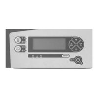
Carrier 30WI Manual (128 pages)
Chiller - Heat Pump Control
Brand:
Carrier
| Category:
Controller
| Size: 4.27 MB
Table of Contents
Table of Contents
2
Important Recommendations
5
Electrical Power Supply
5
Board Controller Specifications
5
Warning
5
Earthing
5
Connection of Sensors
5
Connection of Communication Buses and of the Remote Console
5
Connection of On/Off Inputs
5
General
6
Composition
7
Main Control Board for Machines with One Non-Reversible Refrigerating Circuit
7
Additional Board 1
8
Additional Board 2
8
Control and Display Console
10
Connection Via RS485 Serial Port for CMS or Control Console and Multi Controller Unit
11
Relay Boards
11
Description
12
Main Board
12
Expansion (Additional) Boards 1 and 2
12
Man-Machine Communication
12
Access Levels
13
Selecting an Authorised Access Level
13
Accessing the Various Access Levels
13
Configuring Access Levels on the Controller
14
Management of the Numeric Codes for Accessing Levels 2 and 3
14
Classification of the Menus and Their Functions
15
List of Parameters
16
Management of the Drycooler Controller Parameters
25
Contents of the Menus
26
MAIN Menu
26
SETPOINTS Menu
26
MACHINE STATUS Menu
26
Measured Values Menu
31
MACHINE PARAMETERS Menu
32
ADJUSTMENT PARAMETERS Menu
36
OPERATION PARAMETERS Menu
44
FAULT MEMORY Menu
54
TEST MODE Menu
55
HP Test Per Circuit (from Version V27)
55
Management of the On/Off Inputs
57
Automatic Machine Operation Control
57
Load Shedding Control
57
Water Flow Switch
57
Fan Fault (Circuits 1 and 2)
58
Expansion Valve Fault
59
Phase Controller Fault
60
Pump Fault
60
Compressor Protection
61
Manual HP Pressure Switch Fault on Circuit 1 or 2
61
Setpoint Selection Via On/Off Input
62
Variable Setpoint Via 4 20 Ma Input
62
Operating Mode Selection
63
Management of the Analogue Inputs
64
Temperature Sensor
64
Pressure Sensor
67
Management of the Water Pumps
69
Pump 1
69
Pump 2
69
Pump Management if P2 = 3 (Reversible Air-To-Water) + Heating Mode + P111 = Boiler
69
Unseizing and Switching the Pumps
69
Actuation of Variable-Speed Pump 1 on Water-To-Water Machines Via the 0/10V Output
70
Winter Protection
72
Frost Protection of Pumps and Heat Exchangers While Unit Is off
72
Water Loop Winter Protection
72
Management of the Functions
73
Management of the Compressor Protections
73
Management of the Time Counters
73
Management of Compressor Start-Up
73
Compressor Stopping Sequence
74
Management of the Reversing Valves
75
Management of Configurable Output P111
75
Self-Adjusting Functions
76
Self-Adjusting Function: Water Frost Limit
76
Self-Adjusting Function: Refrigerant Frost Limit
76
Self-Adjusting Function: HP Pressure Limit
76
Self-Adjusting Function: Discharge Protection, Circuit 1 or 2
77
Self-Adjusting Function: Minimum HP, Circuit 1 or 2
77
Self-Adjusting Function for High Water Return Temperatures
77
Fault Functions
78
Water Frost Limit Fault on Circuits 1 and 2
78
Refrigerant Frost Limit Fault on Circuits 1 and 2
78
HP Pressure Fault, Circuits 1 and 2
79
Discharge Temperature Fault, Circuit 1 or 2
79
LP Fault on Circuit 1 or 2
80
Management of Superheat Faults
81
Controls
82
Main Control in Cooling and Heating Modes
82
Water Temperature Setpoint Adjustment
83
Adjustment of Water Temperature Setpoint if P7 ≠ INVERTER
83
Adjustment of Setpoint for the Water Supply and Return Temperatures (P141 = 1 or 2) if P7 = INVERTER
86
Storage Control
88
Control Setpoint (P251) Management
88
Automated Self-Regulating Control
89
Control for Bus Connection to the Drycooler Controller in FREECOOLING Mode
89
Control of Condensing Pressure for Air-Cooled Units
90
Control During Normal Operation or On/Off Control
90
Forced and Self-Adjusting Control
91
Fan Speed Control
91
Low Noise Control (Single-Fan Units Only)
95
Total Recovery Control
96
Management of the Air Blades if P10 = Centrifugal
96
Control of Condensing Pressure for Water-To-Water Units
98
Operation with a Two-Way Valve
98
Operation with a Three-Way Valve
98
Restriction of Operation of the Machines Based on the Outdoor Temperature
99
Restriction to the Minimum Air Temperature in Heating Mode
99
Restriction to the Maximum Air Temperature in Cooling Mode
99
Restriction to the Maximum Air Temperature in Heating Mode
100
Restriction to the Minimum Air Temperature in Cooling Mode
100
Management of the Auxiliary Heater Board and the Electric Auxiliary Heaters
101
Management of the Back-Up Boiler
103
Master/Slave Control
104
Case of Two Parallel-Connected Machines
104
Actuation of the Electronic Expansion Valve
108
With Alco Driver and Display
108
With VCM Driver
108
Important Information Regarding the Control of an Inverter Compressor
110
Defrosting of the Evaporator Coils
112
Hourly Programming
113
Presentation
113
Definition of the Programming Stages
113
Definition of Holiday Zones
113
Operation
113
Management of a Refrigerant Fluid Leak and Leak Fault Detector
116
Link between the CAREL Detector and the Controller
116
Management of Faults When a Leak Is Detected by the CAREL Unit if P104 = YES
116
Management of Faults if Communication (Bus) with the CAREL Unit Is Lost if P104 = YES
116
Management of Sensor Faults in the CAREL Detector if P104 = YES
117
Reading Parameters
117
Management of Electrical Power
118
Management of Load Shedding on a Power Input Threshold
118
Reading Parameters
119
Display in the Measured Values and Machine Status Menus
119
Management of Maintenance Reminder Display
120
FGAS Tightness Check Reminder
120
Maintenance Reminder
120
Useful Information for both Functions
121
Communication Protocol
122
Registers Accessible by Customer
123
Customer Access Bits
124
Advertisement
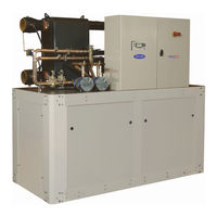
Carrier 30WI Installation, Operation And Maintenance Instructions (28 pages)
HEAT PUMPS AND LIQUID COOLERS WITH WATER COOLED CONDENSER
Brand:
Carrier
| Category:
Heat Pump
| Size: 1.8 MB
Table of Contents
Table of Contents
3
Introduction
4
Transporting the Unit
4
Receipt of Goods
4
Checking the Equipmentl
4
Identifying the Equipment
4
Safety Instructions
5
Machine Compliance
5
Unit Location
6
Handling and Positioning
6
Installing the Unit
7
Dimensions and Floor Mounting of the Frames
7
Anti-Vibration Mounts (Not Supplied by CARRIER)
7
Operating Limits
8
Operating Range
8
Limits
8
Evaporator Limits
8
Minimum/Maximum Water Flow Rates
8
Location of the Main Components
9
Main Components of the Refrigerating Circuit
9
Hydraulic Connections
10
Glycol/Water-MIX Antifreeze Protection
11
Electrical Connections
12
Power Connection
12
Customer Connection for Remote Control Functions
12
Control and Safety Devices
14
Electronic Control and Display Module
14
Main Functions
14
Safety Device Management
14
Phase Controller Option
15
Location of the Safety Sensors and Devices
16
Adjusting the Control and Safety Devices
17
Commissioning
17
Essential Points that Must be Checked
18
Technical and Electrical Specifications
19
Servicing and Maintenance
21
AQUASNAP 30WI Operating Readings
21
Unit Maintenance and Servicing
21
Ecodesign
23
Arrêt Définitif
23
Troubleshooting Operating Problems
24
Schematic Installation Diagram
25
Cooling Installation with Drycooler
25
Cooling Mode (Heating and Cooling)
25
Heating Mode (Heating and Cooling)
26
Advertisement
Related Products
Carrier 33ZCFANTRM
Carrier 38AKS
Carrier 38AK
Carrier 38CQ
Carrier 33ZCFANCOL
Carrier 37HS1
Carrier 37HS4
Carrier 39HXC
Carrier 39HXV
Carrier 36CB IQIDC
Carrier Categories
Air Conditioner
Heat Pump
Furnace
Thermostat
Chiller
More Carrier Manuals
Login
Sign In
OR
Sign in with Facebook
Sign in with Google
Upload manual
Upload from disk
Upload from URL