Table of Contents
Advertisement
Quick Links
Configuration Instructions
CONTENTS
SAFETY CONSIDERATIONS . . . . . . . . . . . . . . . . . . . . . . 1
GENERAL . . . . . . . . . . . . . . . . . . . . . . . . . . . . . . . . . . . . . . .1,2
INSTALLATION . . . . . . . . . . . . . . . . . . . . . . . . . . . . . . . . 2-26
Inspection. . . . . . . . . . . . . . . . . . . . . . . . . . . . . . . . . . . . . . . . 2
PremierLink Controller Hardware. . . . . . . . . . . . . . . . . 2
Field-Supplied Hardware . . . . . . . . . . . . . . . . . . . . . . . . . 2
Mount PremierLink Control. . . . . . . . . . . . . . . . . . . . . . . 2
PremierLink Controller Inputs and Outputs . . . . . . 3
Control Wiring. . . . . . . . . . . . . . . . . . . . . . . . . . . . . . . . . . . . 3
Install Sensors . . . . . . . . . . . . . . . . . . . . . . . . . . . . . . . . . . . 9
INSTALLATION
INSTALLATION
• INDOOR AIR QUALITY CO
INSTALLATION
• OUTDOOR AIR QUALITY CO
INSTALLATION
Connect to CCN Communication Bus . . . . . . . . . . . 18
Enthalpy and Differential Enthalpy Control . . . . . . 18
SENSOR
Economizer . . . . . . . . . . . . . . . . . . . . . . . . . . . . . . . . . . . . . 21
Economizer with Johnson 4 to 20 mA
Actuator . . . . . . . . . . . . . . . . . . . . . . . . . . . . . . . . . . . . . . 24
• SWITCH SELECTION
• WIRING
START-UP . . . . . . . . . . . . . . . . . . . . . . . . . . . . . . . . . . . . 26-28
Perform System Check-Out . . . . . . . . . . . . . . . . . . . . . 26
Initial Operation and Test. . . . . . . . . . . . . . . . . . . . . . . . 26
Install Navigator™ Display Module . . . . . . . . . . . . . 26
Password Protection . . . . . . . . . . . . . . . . . . . . . . . . . . . . 28
Forcing Values and Configuring Items . . . . . . . . . . 28
Manufacturer reserves the right to discontinue, or change at any time, specifications or designs without notice and without incurring obligations.
PC 111
Book 1
4
Tab
3a
2a
Installation, Start-Up and
Part Number 33
Page
SENSOR
2
SENSOR
2
2
SENSOR
2
Catalog No. 533-80072
Printed in U.S.A.
PremierLink™
Retrofit Split System
CSPREMLK
CONFIGURATION . . . . . . . . . . . . . . . . . . . . . . . . . . . . 28-42
Points Display Screen . . . . . . . . . . . . . . . . . . . . . . . . . . . 28
Thermostat Control Input Screen. . . . . . . . . . . . . . . . 30
Alarm Service Configuration Screen . . . . . . . . . . . . 30
Controller Identification Screen . . . . . . . . . . . . . . . . . 31
Holiday Configuration Screen . . . . . . . . . . . . . . . . . . . 31
Occupancy Configuration Screen . . . . . . . . . . . . . . . 32
Set Point Screen . . . . . . . . . . . . . . . . . . . . . . . . . . . . . . . . 32
Service Configuration Selection Screen. . . . . . . . . 33
PremierLink Configuration Screen . . . . . . . . . . . . . . 37
Occupancy Maintenance Screen . . . . . . . . . . . . . . . . 39
Maintenance Screen . . . . . . . . . . . . . . . . . . . . . . . . . . . . 40
SAFETY CONSIDERATIONS
SAFETY NOTE
Air-handling equipment will provide safe and reliable service
when operated within design specifications. The equipment
should be operated and serviced only by authorized person-
nel who have a thorough knowledge of system operation,
safety devices and emergency procedures.
Good judgement should be used in applying any manufac-
turer's instructions to avoid injury to personnel or damage to
equipment and property.
Disconnect all power to the unit before performing mainte-
nance or service. Unit may automatically start if power is
not disconnected. Electrical shock and personal injury
could result.
Damage to equipment may result. An individual field-
supplied 24-vac power transformer is required for each
PremierLink controller. The transformer must be less than
100 va to meet UL (Underwriters' Laboratories) Class 2.
GENERAL
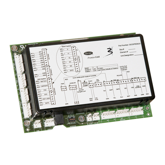
The PremierLink Controller is a field retrofit split system
control compatible with the Carrier Comfort Network (CCN).
This control is designed to allow users the access and ability to
change factory-defined settings thus expanding the function of
the standard unit control board. The complete PremierLink
package (part number 33CSPREMLK) consists of a control
circuit board with plastic cover and label, wire harnesses, spade
connectors, wire nuts and 4 mounting screws.
Form 38-54SI
Pg 1
Controller
Page
11-02
Replaces: 38-52SI
Advertisement
Table of Contents

Related Manuals for Carrier PREMIERLINK 33CSPREMLK


Summary of Contents for Carrier PREMIERLINK 33CSPREMLK
-
Page 1: Table Of Contents
100 va to meet UL (Underwriters’ Laboratories) Class 2. The PremierLink Controller is a field retrofit split system control compatible with the Carrier Comfort Network (CCN). This control is designed to allow users the access and ability to change factory-defined settings thus expanding the function of the standard unit control board. -
Page 2: Location
3-wire connection to the communication bus. User interfaces available for use with the CCN system are PC’s equipped with Carrier user interface software such as Service Tool, Comfort- VIEW™, or ComfortWORKS® software. When used as part of the CCN, other devices such as the CCN data transfer, Linkage Thermostat, or Comfort Controller can read data from or write data to the PremierLink retrofit controller. -
Page 3: Premierlink Controller Inputs And Outputs
PremierLink controller can result. Control Wiring — The PremierLink controller can be connected to either a Carrier-approved thermostat or CCN compatible temperature sensor. 1. Turn off power to the control box. 2. Strip the ends of the red, white, and black conductors of the communication bus cable. - Page 4 PremierLink Connections HS3/EXH/RVS CMP2 CMP1 LEGEND CCR — Capacity Control Relay (If Equipped) CCSV — Capacity Control Valve, Indoor Coil (If Equipped) — Indoor-Fan Contactor LLSV — Liquid Line Solenoid Valve NOTE: Configure AC to “0”. Fig. 2A — Typical PremierLink™ Control Wiring — 38AK,AKS,ARZ,ARS007-012 Units PremierLink Connections HS3/EXH/RVS CMP2...
- Page 5 PremierLink Connections HS3/EXH/RVS CMP2 CMP1 LEGEND CCR — Capacity Control Relay (If Equipped) CCSV — Capacity Control Valve, Indoor Coil (If Equipped) — Indoor-Fan Contactor LLSV — Liquid Line Solenoid Valve NOTE: Configure AC to “0”. Fig. 2C — Typical PremierLink™ Control Wiring — 38ARD012 Units PremierLink Connections HS3/EXH/RVS CMP2...
- Page 6 PremierLink Connections HS3/EXH/RVS CMP2 CMP1 LEGEND IFC — Indoor-Fan Contactor Fig. 2E — Typical PremierLink™ Control Wiring — 38AH024-034 Units PremierLink Connections HS3/EXH/RVS CMP2 CMP1 LEGEND CR — Control Relay IFC — Indoor-Fan Contactor IFR — Indoor-Fan Relay LLS — Liquid Line Solenoid —...
- Page 7 PremierLink Connections HS3/EXH/RVS CMP2 CMP1 LEGEND CR — Control Relay (Field-Supplied) IAQ — Indoor-Air Quality IFC — Indoor-Fan Contactor NOTES: 1. Configure AC to “1” for heat pump units. 2. Configure AUXOUT to “3’ for reversing valve. 3. Configure PremierLink control for 2-stage heat and single-stage cool. 4.
- Page 8 IFC — Indoor-Fan Contactor NOTES: 1. Configure AC to “1” for heat pump or “0” for air conditioner. 2. When using controller for DCV, if IAQ priority is set to HIGH, the controller will use a stage of heat for temperature tempering.
-
Page 9: Install Sensors
SPACE TEMPERATURE (SPT) SENSOR INSTALLA- TION — There are three types of SPT sensors available from Carrier: The 33ZCT55SPT space temperature sensor with timed override button, the 33ZCT56SPT space temperature sensor with timed override button and set point adjustment, and... -
Page 10: Space Temperature (Spt) Sensor
Table 3 — Thermistor Resistance vs Temperature Values for Space Temperature Sensor, Supply Air Temperature Sensor, and Outdoor Air Temperature Sensor TEMP TEMP –40 –40 –35 –31 –30 –22 –25 –13 –20 –4 –15 –10 –5 RED(+) WHT(GND) BLK(-) BRN (GND) BLU (SPT) Fig. -
Page 11: Field Wiring
FIELD WIRING T58 SENSOR 24 VAC CCN- BLACK (-) WHITE (GND) CCN+ RED (+) BLACK (-) WHITE (GND) RED (+) Fig. 5 — T58 Communicating Sensor Typical Wiring (33ZCT58SPT) Perform the following steps if state or local code requires the use of conduit, or if your installation requires a cable length of more than 8 ft: 1. - Page 12 SENSOR 1 SPACE TEMPERATURE AVERAGING — 4 SENSOR APPLICATION LEGEND Factory Wiring Field Wiring SPACE TEMPERATURE AVERAGING — 9 SENSOR APPLICATION SENSOR 2 SENSOR 1 SENSOR 4 SENSOR 7 Fig. 6 — Space Temperature Averaging SENSOR 3 SENSOR 3 SENSOR 2 SENSOR 6 SENSOR 5 SENSOR 8...
-
Page 17: Supply Air Temperature (Sat) Sensor
Fig. 11 — Typical Mounting Location for Supply Air Temperature (SAT) Sensor On Split System Units H G 24 VAC 24 VDC 8 7 6 5 4 3 2 1 Fig. 12 — Outdoor Air Quality (CO (33ZCSENCO2) — Typical Wiring Diagram Fig. -
Page 18: Enthalpy Switch/Receiver
4000 ft, with no more than 60 total devices on any 1000-ft section. Optically isolated RS-485 repeaters are required every 1000 ft. NOTE: Carrier device default is 9600 baud. COMMUNICATION BUS WIRE SPECIFICATIONS — The CCN Communication Bus wiring is field-supplied and field-installed. - Page 19 -in. TEK screws. Insert the screws through the holes in the sides of the enthalpy switch/receiver. Wiring — Carrier recommends the use of 18 to 22 AWG twisted pair or shielded cable for all wiring. All connections must be made with -in.
-
Page 20: Outdoor And Return Air Enthalpy
Fig. 20 — Typical Wiring Schematic — Carrier Rooftop Unit with PremierLink™ Controls Connect the 4-20 mA In terminal on the enthalpy switch/ receiver to the 4-20 mA Out terminal on the return air enthalpy sensor. Connect the 24-36 VDC Out terminal on the enthalpy switch/receiver to the 24-36 VDC In terminal on the return air enthalpy sensor. -
Page 21: Q769B
24 VAC OUTPUT FROM N/C CONTACT WHEN THE OUTDOOR ENTHALPY IS LESS THAN THE INDOOR ENTHALPY (ENABLE ECONOMIZER) 24 VAC OUTPUT FROM N/O CONTACT WHEN THE OUTDOOR ENTHALPY IS GREATER THAN THE OUTDOOR ENTHALPY (ENABLE ENERGY RECYCLER) LEGEND N/C — Normally Closed N/O —... - Page 22 BRACKET HH57AC078 ENTHALPY SENSOR (USED WITH ENTHALPY CONTROL FOR DIFFERENTIAL ENTHALPY OPERATION) MOUNTING PLATE Fig. 22 — Differential Enthalpy Control, Sensor and Mounting Plate (33AMKITENT006) Fig. 23 — Location of Differential Enthalpy Controller and Return Air Enthalpy Sensor (40RM Unit Shown) GRAY GRAY NOTES:...
-
Page 24: Actuator
24 VAC 24 VAC TRANSFORMER SENSOR Q769B ADAPTER MIN. ISOLATOR M7415 ACTUATOR Fig. 26 — PremierLink™ Control Wiring to Q769B Adapter and Actuator 24 VAC 24 VAC TRANSFORMER (SEPARATE, FIELD-SUPPLIED) SENSOR Q769C ADAPTER 500 OHM MIN. RESISTOR M7415 ACTUATOR Fig. 27 — PremierLink Control Wiring to Q769C Adapter and Actuator Economizer with Johnson 4 to 20 mA Actua- tor —... - Page 25 WIRE HARNESS FROM ACTUATOR Gray Output 20 VDC at 25 mA White/Red Feedback 0 (2)-10 or 6-9 VDC Input 0 (2)-10 or 6-9 VDC, 0 (4)-20 mA Yellow 24 VAC/VDC White Fig. 29 — PremierLink™ Controller Wiring to Johnson Actuator With Wire Harness ACTUATOR 50TJ400812 M9206-GGC-2...
-
Page 26: Start-Up
The unit must be electrically grounded in accordance with local codes and NEC ANSI/NFPA 70 (American National Standards Institute/National Fire Protection Association). Use the Carrier network communication software to start up and configure the PremierLink™ controller. Changes can be made using the ComfortWORKS ware, ComfortVIEW™... - Page 27 OPERATION — To use the Navigator, plug the RJ14 connec- tor into the RJ14 port. On power up, the Navigator displays: PremierLink Navigator Carrier The Navigator will upload the appropriate display tables from PremierLink™ controller. A ‘Communication failure’ message will be displayed if any errors are encountered. Check the wiring at the connector.
-
Page 28: Password Protection
The following sections describe the computer configuration screens which are used to configure the PremierLink™ con- troller. The screens shown may be displayed differently when using different Carrier software. Points Display Screen — The Points Display screen is used to monitor and change the PremierLink controller set points. - Page 29 DESCRIPTION Space Temperature Supply Air Temperature Outdoor Air Temperature Control Setpoint Cooling % Total Capacity Heating % Total Capacity Economizer Active Supply Fan Relay Supply Fan Status Economizer Position Current Min Damper Pos Filter Status Remote Occupied Mode Heat Stage 1 Heat Stage 2 Heat 3/Exhaust/Rev Valve Enthalpy...
-
Page 30: Thermostat Control Input Screen
HEAT STAGE 2 — The Heat Stage 2 point provides the state of the Heating 2 output. Heating Stage 2: Display Units: Discrete ASCII Default Value: Display Range: Off/On Network Access: Read Only HEAT STAGE 3, EXHAUST FAN, OR REVERSING VALVE —... -
Page 31: Controller Identification Screen
Table 8 — Thermostat Control Input Display DESCRIPTION Y1 - Call for Cool 1 Y2 - Call for Cool 2 W1 - Call for Heat 1 W2 - Call for Heat 2 G - Call for Fan ALARM RE-ALARM TIME — This decision is used to con- figure the number of minutes that will elapse between re-alarms. -
Page 32: Occupancy Configuration Screen
DURATION — The Duration field indicates how long the holiday will last (in days). Duration: Range: 0 to 365 Default Value: As an example, if a Holiday is configured for Month 2, Day 5, Duration 2, then the Holiday will start February 5 and end February 7. -
Page 33: Service Configuration Selection Screen
UNOCCUPIED HIGH — The Unoccupied High set point de- scribes the high temperature limit of the space during Unoccu- pied mode. Unoccupied High: Units: Degrees F (Degrees C) Range: 45.0 to 99.9 Default Value: 90.0 HIGH OAT LIMIT FOR IAQ PRE-OCCUPANCY PURGE —... - Page 34 Table 14 — Service Configuration Selection DESCRIPTION VALUE UNITS Cooling PID Proportional Gain Integral Gain Derivative Gain Starting Value 70.0 Staged Cooling Total Number of Stages Stage 1 Time Guard Enable Stage 2 Time Guard Enable Stage 3 Time Guard Disable Heating PID Proportional Gain...
- Page 35 The integral gain affects the PID calculation; an increase will make the IAQ submaster reference change greater as the error in indoor air quality increases. The integral gain should be selected to eliminate proportional droop without overshoot. Enter the desired integral gain for the Indoor Air Quality con- trol algorithm.
- Page 36 The DXCTLO should be turned OFF (to ignore the DXLOCK setpoint) in applications where there is either no OAT sensor (local or broadcast) or the OAT sensor has failed. For Version 1.3 — If there is a valid OAT sensor reading and DXCTLO is set to “OFF”, compressor cooling will NOT be allowed.
-
Page 37: Premierlink Configuration Screen
1), Y2 (cooling stage 2), W1 (heating stage 1), W2 (heat- ing stage 2), and G (indoor fan) inputs. The CCN mode allows the controller to integrate into a Carrier Comfort Network. Operating Mode: Range: 0 for TSTAT 1 for CCN... - Page 38 GLOBAL SCHEDULE BROADCAST — The Global Sched- ule Broadcast setting configures the controller to broadcast or receive a global schedule. If set to Yes, the controller will act as a global schedule master and its schedule will be broadcast to the CCN.
-
Page 39: Occupancy Maintenance Screen
Low Reference specifies Low Point of the Outdoor IAQ Sensor Range in ppm. Low Reference: Units: PPM (parts per million) Range: 0 to 5000 Default Value: High Reference specifies High Point of the Outdoor IAQ Sensor Range in ppm. High Reference: Units: PPM (parts per million) Range: 0 to 5000... -
Page 40: Maintenance Screen
NEXT UNOCCUPIED DAY — The Next Unoccupied Day point displays the day of week when the next unoccupied peri- od will begin. This point is used with the Next Unoccupied Time so the user will know when the next unoccupied period will occur. - Page 41 IAQ PRE-OCCUPANCY PURGE — Indicates that the pre- occupancy purge mode is currently active. Pre-occupancy Purge: Display Range: Default Value: Network Access: UNOCCUPIED FREE COOLING — Indicates that unoccu- pied free cooling is in effect. Unoccupied Free Cooling: Display Range: Default Value: Network Access: FIRE SHUTDOWN —...
- Page 42 The Average Occupied Heat Set Point displays the Occupied Heat set point from the Linkage Thermostat. Average Occupied Heat Set Point: Display Units: Degrees F (Degrees C) Display Range: 0.0 to 99.9 Default Value: Network Access: None The Average Occupied Cool Set Point displays the Occu- pied Cool set point from the Linkage Thermostat.
- Page 44 Copyright 2002 Carrier Corporation Manufacturer reserves the right to discontinue, or change at any time, specifications or designs without notice and without incurring obligations. Book 1 PC 111 Catalog No. 533-80072 Printed in U.S.A. Form 38-54SI Pg 44 11-02 Replaces: 38-52SI...
Need help?
Do you have a question about the PREMIERLINK 33CSPREMLK and is the answer not in the manual?
Questions and answers