
Related Manuals for Carrier AQUASNAP 30WI


Summary of Contents for Carrier AQUASNAP 30WI
- Page 1 I N S TA L L AT I O N , O P E R AT I O N A N D M A I N T E N A N C E I N S T R U C T I O N S HEAT PUMPS AND LIQUID COOLERS WITH WATER COOLED CONDENSER 30WI...
-
Page 3: Table Of Contents
7 - HANDLING AND POSITIONING ..............................6 8 - INSTALLING THE UNIT ................................7 8.1 - Dimensions and floor mounting of the frames ........................... 7 8.2 - Anti-vibration mounts (not supplied by CARRIER) ........................7 9 - OPERATING LIMITS ..................................8 9.1 - Operating range ..................................8 9.2 - Limits ......................................8 9.3 ... -
Page 4: Introduction
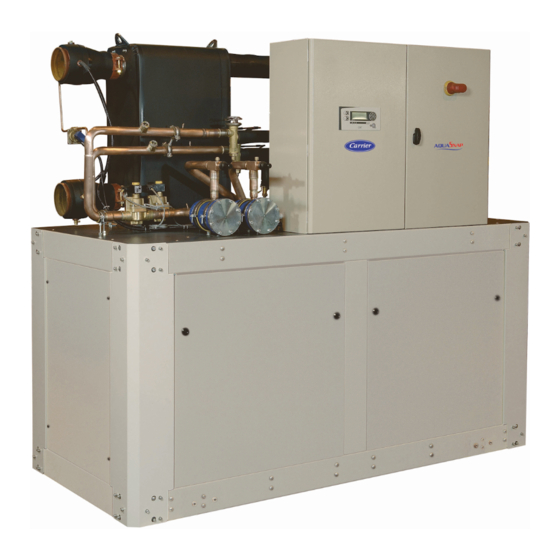
1 - INTRODUCTION AQUASNAP 30WI series water chiller units are designed to meet the air conditioning and heating requirements of residential and office buildings as well as the requirements of industrial processes. AQUASNAP 30WI series units are liquid chillers with water-cooled condensers which guarantee safe and reliable operation in the operating range for which they have been designed. All the units are factory tested and checked. They are supplied with a full refrigerant charge. These units meet standard EN 60-204 and standard EN378-2 as well as the following European directives: - Machinery 2006/42 EC - EMC 2014/30/EU - LVD 2014/35/EU - RoHS 2011/65/EC: - PED 2014/68/EU, see table below... -
Page 5: Safety Instructions
PT=3XPS CF NOTICE 0060 - BP/LP. Mini = Minimum operating pressure in bar. Contient des gaz fluorés à effet de serre / Contains fluorinated greenhouse gases - PSM/MOP = Maximum standard pressure in bar (SP according CARRIER SCS to PED 2014/68/EU). Rte de Thil 01122 Montluel - France - HP Maxi PSM/MOP : For the high pressure circuit: Tél.: (33) 4 72 25 21 21 M ad e in Fr an c e - HP. Maxi = Maximum operating pressure in bar. -
Page 6: Unit Location
• To ensure vibrations transmitted by solid materials are reduced as much as possible, it is strongly recommended to fit anti- vibration mounts between the unit support and frame (see the section on anti-vibration mounts), as well as flexible couplings on the hydraulic piping. • Have an analysis carried out by an acoustics engineer. IMPORTANT: The ambient temperature must not exceed 50°C during the unit’s off cycles. 7 - HANDLING AND POSITIONING To raise the unit, attach the slings to the designated handling holes. The data relating to the centre of gravity and the position of the anchorage points are given on the dimensional drawing. Detailed view of the anchorage point for handling AQUASNAP 30WI Holes for handling Ø 35.2 mm The unit can be handled with a forklift truck (check the maximum permissible load of the forklift). In this case, it is important that the necessary precautions be taken to avoid the unit sliding on the forks of the forklift. You must observe the instructions given on the label affixed to the unit. Failure to observe these instructions may result in the unit tipping over and causing physical injury. CAUTION: - Attach the slings only to the anchorage points intended for this purpose and which are designated on the unit. - Use slings with a suitable lifting capacity and follow the lifting instructions on the drawings provided with the unit. - Caution: the centre of gravity is not necessarily at the middle of the unit and the forces applied to the slings are not always identical. -
Page 7: Installing The Unit
1271 1671 2366 1044 1156 1189 1312 1363 1425 1613 1708 2284 2376 2418 Weight (empty) 1088 1205 1246 1378 1436 1510 1713 1818 2472 2588 2637 Weight (in operation) 8.2 - Anti-vibration mounts (not supplied by CARRIER) Anti-vibration mounts must be installed beneath the unit for applications that generate extremely low vibrations. (See position (E) of the mounting holes in the floor of the frame on the previous diagram). -
Page 8: Operating Limits
9 - OPERATING LIMITS 9.1 - Operating range The graph below represents the area of application (under full load) of the units. AQUASNAP 30WI Glycol compulsory Evaporator outlet water temperature 9.2 - Limits AQUASNAP 30WI Yes – 5 / 10 Condenser The customer should take all means necessary to achieve a minimum ΔT min. °C / ΔT max. °C water inlet temperature of 25°C on the condenser side. -
Page 9: Location Of The Main Components
Electrical cabinet Electrical cabinet 11 - MAIN COMPONENTS OF THE REFRIGERATING CIRCUIT Compressor A 24V backup battery is built into the driver. It allows the expansion valve to be closed in the event of a power failure. It has a service AQUASNAP 30WI units use hermetically sealed SCROLL life of 8 years. After this time, the battery must be replaced. compressors. Important : the valve must not be moved when there is no refrigerant flow rate. When the system is stopped or evacuated, the start-up potential-free (dry) contact must remain open. The compressor is lubricated with a polyester oil, (POE) type ... -
Page 10: Hydraulic Connections
- Using untreated or incorrectly treated water may cause - The water must be analysed and, if necessary, treated (we corrosion or erosion or the formation of scale, algae or sludge recommend contacting a qualified water treatment specialist). deposits. CARRIER shall not be held liable for damage resulting from the use of untreated or incorrectly treated water, The analysis will reveal whether the water is suitable for use with or of saline or brackish water. the various materials it will come into contact with and prevent the formation of electrolytic couples: When the unit is used as a heat pump, the maximum water •... -
Page 11: Glycol/Water-Mix Antifreeze Protection
13 - GLYCOL/WATER-MIX ANTIFREEZE PROTECTION The table and the curves below indicate the minimum percentages of glycol with which the system must be provided depending on the freezing point. WARNING : The glycol concentration must protect the fluid at least 6°C below the water outlet temperature specified for the evaporator to allow correct setting of the minimum pressure controller at the evaporator. Glycol concentration required Volume concentration in % Freezing point °C Ethylene glycol Minimum water outlet °C Freezing point °C Propylene glycol Minimum water outlet °C Important: The values are given for guidance only, according to the standard characteristics of the MEG. These may vary depending on the MEG manufacturer, therefore it is important to refer to the manufacturer’s data to ensure protection is provided to the required temperature. For a glycol concentration greater than 40%, a special pump must be used. Graph of minimum freezing and operating temperatures Volume concentration in % Minimum operating temperature Freezing temperature B Monopropylene glycol D Monopropylene glycol C Monoethylene glycol E Monoethylene glycol... -
Page 12: Electrical Connections
14 - ELECTRICAL CONNECTIONS 14.1 - Power connection The units are designed in accordance with the requirements of Once the size of the wires has been selected, the installer must European standard EN 60204-1. determine any changes needed on site to facilitate connection. - Wiring must be selected based on: They comply with the requirements of the machinery and • The maximum rated current (refer to the “Electrical EMC directives. specifications”). All wiring must be connected in accordance with the codes and • The distance between the unit and its power source. regulations that apply to the installation site (e.g. NFC 15100 in • The protection to be fitted at the power source. France). - Page 13 14 - ELECTRICAL CONNECTIONS General fault alarm: Display for operation at full power (if P111 = max P) Connector Connector 9 10 11 15 16 11 12 13 14 15 16 J3 (CPU) J3 (CPU) 230 V 230 V Alarm Connect the signalling of the unit operating at max. output to Remote control: Connect the unit’s general fault reporting or alarm ...
-
Page 14: Control And Safety Devices
15 - CONTROL AND SAFETY DEVICES 15.1 - Electronic control and display module All units in the range are fitted with a CHILLER/HEATPUMP CONTROL microprocessor-controlled electronic control and display module. The electronic module controls the operation of the compressors. Thus, depending on the difference between the cold water (or hot water) return temperature and the setpoint temperature, the electronic module will activate or deactivate the compressors in series. In a standard configuration of the unit, the cold water or hot water control sensor is placed on the evaporator water return (chilled water production use) or condenser (heat pump use). 15.2 - Main functions ■ Water temperature control: - Evaporator chilled water. -
Page 15: Phase Controller Option
15 - CONTROL AND SAFETY DEVICES Evaporator water circulation controller Every unit is fitted with a water circulation control device as standard. Thus, if the water flow is insufficient, the power supply to the compressor(s) is cut and an LED indicates the fault on the regulator console. Internal compressor protection Every model in the range is protected against overheating of the electric motor and high discharge temperatures. The units are equipped with compressors with internal protection against missing phases and phase reversal. On all models, an optional phase controller may also be added if the customer wishes. Discharge sensor Each unit includes one discharge sensor per refrigerating circuit as standard. This sensor located on the discharge piping makes it possible for the user to view the discharge temperature value and enables the electronic module to provide a safety function. If the discharge temperature exceeds the maximum temperature threshold set in the regulator, the power supply to the compressor(s) for the refrigerating circuit concerned is cut and the fault is indicated by an LED on the regulator console. Overpressure protection Each refrigerating circuit in each unit is protected against the risk of overpressure resulting from fire. ■ Fire valves - The fire valve protect the HP and LP circuits against overpressure caused by an increase in the outdoor temperature, when the unit is off. (E.g.: external fire) - This fire valve is not considered a safety device as defined in section 2.11 of appendix 1 of the pressure equipment directive. ■ Allowable pressure (PS) LP side - The LP value (given on the name plate) corresponds to the situation with the unit switched off. This value is given according to the pressure/temperature ratio with an outdoor temperature of 50°C, depending on the unit. These temperatures correspond to the least favourable situation the unit could be subjected to, excluding an external fire. The LP side pipes are sized for the maximum allowable pressure. -
Page 16: Location Of The Safety Sensors And Devices
15 - CONTROL AND SAFETY DEVICES 15.5 - Location of the safety sensors and devices AQUASNAP 30WI 700V to 1600V COILED IN THE CABINET Pressure- reducing regulator Schrader valve CIRCUIT 1 CIRCUIT 2 Pressure- OPTION reducing Suction valves regulator Schrader ... -
Page 17: Adjusting The Control And Safety Devices
15 - CONTROL AND SAFETY DEVICES 15.6 - Adjusting the control and safety devices Units Function Electrical symbol Settings Adjust the setpoint according to the outdoor Outdoor sensor temperature Chilled water inlet sensor Control of the unit on the water return Chilled water outlet manifold Unit control if controller on water outlet sensor Controller for CHILLER/HEATPUMP CONTROL Hot water inlet sensor... -
Page 18: Essential Points That Must Be Checked
(antifreeze protection, crankcase heater). inlets will be high. Locate the leak, completely drain the refrigerant NOTE: charge using a recovery machine, and fill the unit with a new charge. AQUASNAP 30WI machines operate using R410A. It is essential Repair the leak, pressure test the unit (do not exceed the maximum that technicians use equipment which is compatible with R410A. service pressure on the low-pressure end) then refill the unit. The refrigerant must be liquid and charged via the liquid charging valve. 16.2 - Essential points that must be checked The amounts of refrigerant indicated on the data plate must be added ... -
Page 19: Technical And Electrical Specifications
17 - TECHNICAL AND ELECTRICAL SPECIFICATIONS AQUASNAP 30WI 700V 800V 900V 1000V 1100V 1200V Compressor Type Hermetic SCROLL (2900 rpm) Quantity Start-up mode Direct in line in series Refrigerant oil type POE 160SZ Oil capacity (circ.1 + circ. 2) 6,7 + 6,7 6,7 + 7,2 7,2 + 7,2 Number of refrigerating circuits Refrigerant R410A equivalent tonne 57,42 63,68... - Page 20 17 - TECHNICAL AND ELECTRICAL SPECIFICATIONS AQUASNAP 30WI 1400V 1600V 1800V 2100V 2400V Compressor Type Hermetic SCROLL (2900 rpm) Quantity Start-up mode Direct in line in series Refrigerant oil type POE 3MAF Oil capacity (circ.1 + circ. 2) 6,3 + 6,3 6,3 + 6,3 + 6,3 Number of refrigerating circuits Refrigerant R410A equivalent tonne 88,74 93,96 129,46 139,90 141,98 Refrigerant charge (circ. 1 + circ. 2)
-
Page 21: Servicing And Maintenance
18 - SERVICING AND MAINTENANCE 18.1 - AQUASNAP 30WI operating readings Date/Time Suction pressure Intake temperature °C Compressor Condensing pressure Condensing temperature °C Discharge inlet temperature °C Liquid outlet temperature °C Water-cooled condenser Water inlet temperature °C Water outlet temperature °C Water inlet temperature °C Water outlet temperature °C Evaporator Liquid inlet temperature °C Evaporator outlet temperature °C Nominal voltage... - Page 22 NB : The cleaning intervals are given as a guide and should be check for leaks of refrigerants containing halocarbons such as adapted to each installation. R410A, and its by-products. NOTE : AQUASNAP 30WI machines operate using R410A. It is 18.2.7 - Disassembling the compressor essential that technicians use equipment which is compatible with R410A with a working pressure which is approximately 1.5 times The compressor is fastened to the platform by four dia. 8 mm ...
-
Page 23: Ecodesign
19 - ECODESIGN The sealing test must be carried out in compliance with EC regulation no. 517/2014 relating to certain greenhouse gases. R410A, R134a and R407C are refrigerant gases with the following environmental impact: 1/ No impact on the ozone layer. They have an ODP (Ozone Depletion Potential) index of 0 2/ Impact on the greenhouse effect: Global Warming Potential (GWP) of each gas. - R410A -------- GWP = 2088 - R407C -------- GWP = 1800 - R134a -------- GWP = 1430 Users must ensure that periodic leak testing is carried out by qualified personnel based on the number of tonnes of CO equivalent: ≥ 5 tCO ≥ 50 tCO ≥ 500 tCO Without leak detection system Every 12 months Every 6 months Every 3 months... -
Page 24: Troubleshooting Operating Problems
21 - TROUBLESHOOTING OPERATING PROBLEMS Initial advice: - Faults detected by the safety devices are not necessarily caused by a sudden change in the measurement being monitored. - Taken regularly, readings should make it possible to anticipate future trips. - Perform the checks listed in the table below (next page) if you notice that a measurement deviates from its normal value and gradually moves closer to the safety limit. Important: First and foremost, bear in mind that most faults potentially occurring on the units have simple causes that are often the same for all. Look for these causes first. There are three such causes in particular: • The fouling level of the exchangers • Problems with the fluid circuits • Failures of electric components such as the relay coil or the electric valve etc. Faults Faults Probable causes Instructions - Purge the chilled water circuit. - Check the opening of the chilled water circuit valves. - Air in the chilled water circuit. - Check the direction of rotation of the pump, that there is no - Chilled water flow insufficient. cavitation and that the pump is not too small. Suction pressure too low - Chilled ... -
Page 25: Schematic Installation Diagram
22 - SCHEMATIC INSTALLATION DIAGRAM 22.1 - Cooling installation with drycooler A : Chilled water circuit I : Air bleed B : Recovery water circuit J : Water filter (Compulsory) C : Water filling K : Water hoses D : Expansion vessel L : Thermowell E : Control valve M : Hydraulic 3-way valve F : Drain N : Cleanable heat exchanger G : Shut-off valve O : Safety valve H : Temperature controller 22.2 - Cooling mode (Heating and cooling) -
Page 26: Heating Mode (Heating And Cooling)
22 - SCHEMATIC INSTALLATION DIAGRAM 22.3 - Heating mode (Heating and cooling) A: Chilled water or hot water circuit J: Water filter (compulsory) C: Water filling K: Water hose (compulsory) D: Expansion vessel L: Thermowell E: Control valve M: Well discharge F: Drain N: Hydraulic valve G: Shut-off valve O: Cleanable exchanger I: Air bleed valve P: Safety valve... - Page 28 (latest current version) after an assessment conducted by an authorized independent third party. Please contact your sales representative for more information. Order No: EN7546022-02, 07.2023 Supersedes order No: EN7546022-01, 06.2019 Carrier SCS, Montluel, France. Manufacturer reserves the right to change any product specifications without notice. Printed in the European Union.
Need help?
Do you have a question about the AQUASNAP 30WI and is the answer not in the manual?
Questions and answers