Carrier 33CS Installation, Service And Instructions
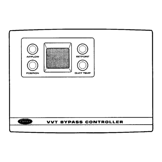
Variable volume and temperature (vvtt) bypass controller
Hide thumbs
Also See for 33CS:
Table of Contents
Advertisement
Quick Links
Troubleshooting Instructions
GENERAL . . . . . . . . . . . . . . . . . . . . . . . . . . . . . . . . . . . 1
INSTALLATION . . . . . . . . . . . . . . . . . . . . . . . . . . . . . 2-7
Bypass Controller Placement . . . . . . . . . . . . . . . . . 2
Mounting Bypass Damper Actuator to Duct . . . . 2
Wiring Requirements . . . . . . . . . . . . . . . . . . . . . . . . . 2
Wiring Connections . . . . . . . . . . . . . . . . . . . . . . . . . . 2
Sensor Adjustment . . . . . . . . . . . . . . . . . . . . . . . . . . . 3
Pressure Sensors . . . . . . . . . . . . . . . . . . . . . . . . . . . . 3
Selection of System Pressure Set Point . . . . . 6
Zone Damper Control . . . . . . . . . . . . . . . . . . . . . . . . 7
OPERATION . . . . . . . . . . . . . . . . . . . . . . . . . . . . . . . 8
BYPASS CONTROLLER CONFIGURATION . . . . . 8
BYPASS CONTROLLER DISPLAY . . . . . . . . . . . . 8-10
Information Display . . . . . . . . . . . . . . . . . . . . . . . . . 10
Bypass Controller Initialization Display . . . . . . . 10
Alternate Information Display . . . . . . . . . . . . . . . . 10
Display Freeze . . . . . . . . . . . . . . . . . . . . . . . . . . . . . . 10
COMMUNICATION . . . . . . . . . . . . . . . . . . . . . . . . . 10,11
Communication Interface . . . . . . . . . . . . . . . . . . . . 10
Device Address . . . . . . . . . . . . . . . . . . . . . . . . . . . . . 10
Device Bus Number . . . . . . . . . . . . . . . . . . . . . . . . . 11
Device Access Security Level . . . . . . . . . . . . . . . . 11
SENSORS . . . . . . . . . . . . . . . . . . . . . . . . . . . . . . . . . 11,12
Sensor . . . . . . . . . . . . . . . . . . . . . . . . . . . . . . . . . . . 11
Pressure Sensor . . . . . . . . . . . . . . . . . . . . . . . . . . . . 11
Zone Temperature Monitoring . . . . . . . . . . . . . . . . 11
Zone Temperature Sensor . . . . . . . . . . . . . . . . . . . 11
Remote Room Temperature Sensor . . . . . . . . . . 12
Indoor-Air Quality Sensor . . . . . . . . . . . . . . . . . . . 12
BYPASS DAMPER MODULATION . . . . . . . . . . . 13-14
Damper Interface . . . . . . . . . . . . . . . . . . . . . . . . . . . . 13
Bypass Damper Mode . . . . . . . . . . . . . . . . . . . . . . . 13
Bypass Damper Modulation . . . . . . . . . . . . . . . . . 13
Changeover Cycle . . . . . . . . . . . . . . . . . . . . . . . . . . 13
Modulation . . . . . . . . . . . . . . . . . . . . . . . . . . . . . . . 14
ZD/RD Actuator . . . . . . . . . . . . . . . . . . . . . . . . . . . . . 14
PS Error Damper Position . . . . . . . . . . . . . . . . . . . 14
Fan On Delay . . . . . . . . . . . . . . . . . . . . . . . . . . . . . . . 14
Fan Off Delay . . . . . . . . . . . . . . . . . . . . . . . . . . . . . . . 14
DIAGNOSTICS . . . . . . . . . . . . . . . . . . . . . . . . . . . . 14-18
Error Code Display . . . . . . . . . . . . . . . . . . . . . . . . . . 14
System Errors (SE) . . . . . . . . . . . . . . . . . . . . . . . . . . 15
Storage Failure (SF) Errors . . . . . . . . . . . . . . . . . . 15
Manufacturer reserves the right to discontinue, or change at any time, specifications or designs without notice and without incurring obligations.
Book 1
4
PC 111
Tab
11a 13a
Variable Volume and Temperature (VVT )
Installation, Service and
CONTENTS
Page
Catalog No. 809-246
Printed in U.S.A.
Bypass Controller
Hardware Failure (HF) Errors . . . . . . . . . . . . . . . . 16
Bypass Controller Reset . . . . . . . . . . . . . . . . . . . . . 18
ALARM OPTIONS . . . . . . . . . . . . . . . . . . . . . . . . . . . 18
Equipment Priority . . . . . . . . . . . . . . . . . . . . . . . . . . 18
Communication Failure Retry Time . . . . . . . . . . . 18
Re-Alarm Time . . . . . . . . . . . . . . . . . . . . . . . . . . . . . . 18
Alarm Routing Control . . . . . . . . . . . . . . . . . . . . . . 18
Alarm System Name . . . . . . . . . . . . . . . . . . . . . . . . 18
ALARM DESCRIPTION . . . . . . . . . . . . . . . . . . . . . 18,19
Indoor-Air Quality Status Alarm . . . . . . . . . . . . . . 18
NETWORK ACCESSIBLE VARIABLES . . . . . . . . 19
TROUBLESHOOTING . . . . . . . . . . . . . . . . . . . . 19-21
General Operating Problems . . . . . . . . . . . . . . . . . 19
Bypass Controller Communication
Problems . . . . . . . . . . . . . . . . . . . . . . . . . . . . . . . . . 21
INDEX . . . . . . . . . . . . . . . . . . . . . . . . . . . . . . . . . . . . . . 22
GENERAL
This manual provides detailed explanations of the opera-
tion of the Carrier Comfort System bypass controller and
each configurable function. The configurable functions al-
low the operation of the bypass controller to be adjusted to
match specific user needs and system requirements.
The bypass controller is the pressure moderator of the VVT
system. The pressure moderation ability of the bypass con-
troller makes a zoning system with a constant volume HVAC
unit possible. The bypass controller maintains system static
pressure based on the used-configured set point. The bypass
controller regulates system static pressure by opening its damper
when it measures a pressure above the system set point and
closing its damper when it measures a system pressure be-
low the system set point. If the system static pressure is within
3% of the system set point, the damper will remain at its
present position.
The bypass controller will receive the system mode from
the monitor thermostat and will modulate its damper ac-
cording to user-configured settings, system mode, and sen-
sor information. Only one bypass controller should be used
per one monitor thermostat.
NOTE: The 33CSBC--00 bypass controller will only work
with 33CSPS--01 and 33CSPS--02 pressure sensors.
NOTE: The Comfort System (33CS) bypass controller is not
compatible with a VVT Generation II Enhanced or Pre-
Enhanced device. The Carrier 33CS VVT system will not
support Enhanced or Pre-Enhanced devices.
Form VVT-3SI
Pg 1
33CS
Page
7-95
Replaces: New
Advertisement
Table of Contents

Related Manuals for Carrier 33CS


Summary of Contents for Carrier 33CS
-
Page 1: Table Of Contents
Fan Off Delay ....... 14 NOTE: The Comfort System (33CS) bypass controller is not compatible with a VVT Generation II Enhanced or Pre- DIAGNOSTICS . -
Page 2: Installation
(pressure sensor and indoor-air pass controller. quality [IAQ] sensor). All wiring connections must be made Call the local Carrier representative if more information correctly before the bypass controller will function. is needed about wiring the VVT System or the bypass Bypass Controller Placement —... -
Page 3: Sensor Adjustment
The duct temperature sensor and wiring interfaced to a 33CS pressure sensor. The pressure sensor is part of the damper actuator. No wiring is required. measures actual system static pressure. - Page 4 NOTE: All wiring is field-supplied. → Fig. 2 — Bypass Controller Wiring Connections...
- Page 5 IAQ — Indoor-Air Quality Fig. 3 — Damper Actuator Sensor Wiring LEGEND PCB — Printed Circuit Board PSP — Pressure Static Pickup → Fig. 4 — Bypass Damper and Pressure Sensor Installation...
-
Page 6: Calibration Pressure Set Point And Selection Of System Pressure Set Point
stable system pressure can be obtained. By adjusting the minimum and maximum damper positions at individual zones, the system can be adjusted to balance airflow and obtain an acceptable noise level. The bypass damper will display the highest address found in its scan. 2. -
Page 7: Zone Damper Control
• A "CE" indicates that there is a communication problem Zone Damper Control — Zone damper control allows between the bypass controller and the device at the ad- the bypass controller to position each zone damper associ- dress shown. ated with its system. Each zone damper can be indepen- •... -
Page 8: Bypass Controller Stand-Alone
Computer Configuration — To configure the bypass Alone mode, communications with a monitor thermostat is controller on the network, Carrier network software must be not required. The bypass controller should be addressed out- running. side the scanning range of the monitor thermostat. During Stand-Alone mode, the bypass controller operates in Bypass Damper Pressure mode. - Page 9 → Table 1 — VVT Bypass Controller Categories and Options OPTION DESCRIPTION DEFAULT MINIMUM MAXIMUM CATEGORY 1.0 SET POINTS Cool-Down Set Point (F) Warm-Up Set Point (F) Fahrenheit Temperature Display CATEGORY 2.0 OCCUPANCY SCHEDULE No configuration required. CATEGORY 3.0 DAMPER Maximum Damper Position Minimum Damper Position Pressure Sensor Error Damper Position...
-
Page 10: Information Display
Carrier network for transmitting and receiving infor- bypass controller will display a sequence of information. The mation. The device address is set in category 8, option 1. -
Page 11: Device Bus Number
To access the Duct Temperature Sensor Calibration func- Device Bus Number — There can be different com- tion, set category 5, option 4. The current duct temperature munication buses connected in a single system. There is one is displayed. Use the left upper and lower information primary bus and there can be 239 secondary buses attached buttons to raise or lower the calibration value to the desired to the primary bus. -
Page 12: Remote Room Temperature Sensor
— The Comfort IAQ fea- be added to the connector block for each sensor. See Fig. 11. ture allows the Carrier Comfort system to interface with the economizer (if available) on the HVAC equipment and main- tain the quality of indoor air within acceptable limits. An... -
Page 13: Bypass Damper Modulation
3% of the system pressure set point. operation of the bypass damper as a member of a Carrier If system static pressure is within 3% of the system pres- system. -
Page 14: Counterclockwise Open Damper
SYSTEM MODE SELECTION — System mode is selected To configure the Clockwise Open Damper Modulation op- by the associated system controller (monitor thermostat) of tion, set category 3, option 8. Use the left information but- the bypass controller, to control operation of the system heating/ tons to set the option ON or OFF. -
Page 15: System Errors (Se)
→ When the Error Code Display option is ON, an error code Table 3 — Storage Failure (SF) Errors will be displayed when the associated error occurs. Any pre- INFORMATION DEFAULT vious error codes that occurred when the Error Code Dis- ERROR AFFECTED VALUE(S) -
Page 16: Hardware Failure (Hf) Errors
NOTE: If the SF error cannot be cleared, replace the bypass clockwise Open option (category 3, option 8). For controller and configure the new bypass controller to match Carrier ZD and RD dampers the damper blade modulates desired settings. counterclockwise to open. Ensure this option is config- ured correctly. - Page 17 To check the wiring, disconnect the bypass controller and DUCT TEMPERATURE SENSOR OUT OF RANGE — An wiring connector board. Connect the bypass controller and HF05 error is issued when the duct temperature sensor is wiring connector board directly at the damper board. If open or shorted.
-
Page 18: Bypass Controller Reset
A value of 00000000 disables all alarms going out on stantly verifies operation and the information it utilizes. When the CCN. The option is configured through Carrier network it finds a fault in a specified area, the bypass controller resets access software. -
Page 19: Network Accessible Variables
OPERATION — When the CO level exceeds the preset level, BYPASS CONTROLLER the sensor signals the bypass controller. The bypass control- TROUBLESHOOTING ler will wait until the IAQ Alarm Delay option (category 14, The most common operating problems and errors asso- option 3) has expired, then it will issue an SE10. - Page 20 Ribbon Strip Corresponding wire Metal Pins connected to (See diagram) Terminal Block ‘‘TOP’’ 1st Pin SBO + 2nd Pin Red (+ ) 3-Wire Cable 3rd Pin Black (− ) Communication Bus 4th Pin Green (Gnd ) 5th Pin SBO- 6th Pin White 5 Wire Cable 7th Pin...
-
Page 21: Problems
CONTINUOUSLY RESETTING DISPLAY — If the by- 2. Check the configuration of the communication related op- pass controller display continuously resets (zeros rotate), it tions of the monitor thermostat and each device in the is an indication that the bypass controller is continuously go- VVT system. -
Page 22: Index
INDEX Alarm Description, 18 General, 1 Alarm Options, 18 General Operating Problems, 19 Alarm Routing Control, 18 Hardware A/D Failure, 17 Alarm System Name, 18 Hardware Failure (HF) Errors, 16 Alternate Information Display, 10 Hardware NOVRAM Failure, 17 Bypass Controller Communication Problems, 21 Indoor-Air Quality Alarm Delay, 12 Bypass Controller Configuration, 8 Indoor-Air Quality Exceeded Limit Error, 15... - Page 24 Copyright 1995 Carrier Corporation Manufacturer reserves the right to discontinue, or change at any time, specifications or designs without notice and without incurring obligations. Book 1 PC 111 Catalog No. 809-246 Printed in U.S.A. Form VVT-3SI Pg 24 7-95 Replaces: New...
Need help?
Do you have a question about the 33CS and is the answer not in the manual?
Questions and answers
How do you disable hold mode