Table of Contents
Advertisement
Configuration Instructions
Part Numbers 33ZCFANTRM, 33ZCVAVTRM, 33ZCSECTRM
CONTENTS
SAFETY CONSIDERATIONS . . . . . . . . . . . . . . . . . . . . . . 1
GENERAL . . . . . . . . . . . . . . . . . . . . . . . . . . . . . . . . . . . . . . . . 2
INSTALLATION . . . . . . . . . . . . . . . . . . . . . . . . . . . . . . . . 2-29
General . . . . . . . . . . . . . . . . . . . . . . . . . . . . . . . . . . . . . . . . . . 2
Zone Controller Hardware . . . . . . . . . . . . . . . . . . . . . . . . 2
Field-Supplied Hardware . . . . . . . . . . . . . . . . . . . . . . . . . 2
Mount Zone Controller . . . . . . . . . . . . . . . . . . . . . . . . . . . 4
Connect the Power Transformer . . . . . . . . . . . . . . . . . . 7
Connect Airflow Pickups . . . . . . . . . . . . . . . . . . . . . . . . . 7
Install Sensors . . . . . . . . . . . . . . . . . . . . . . . . . . . . . . . . . . 19
Remote Occupancy Contact. . . . . . . . . . . . . . . . . . . . . 26
Connect the Outputs . . . . . . . . . . . . . . . . . . . . . . . . . . . . 26
Modulating Baseboard Hydronic Heating . . . . . . . . 26
Connect the CCN Communication Bus . . . . . . . . . . 26
START-UP . . . . . . . . . . . . . . . . . . . . . . . . . . . . . . . . . . . . 29-31
Perform System Check-Out . . . . . . . . . . . . . . . . . . . . . 29
Network Addressing. . . . . . . . . . . . . . . . . . . . . . . . . . . . . 30
Initial Operation and Test. . . . . . . . . . . . . . . . . . . . . . . . 30
Airflow Check . . . . . . . . . . . . . . . . . . . . . . . . . . . . . . . . . . . 30
Fan and Heat Configuration and Test. . . . . . . . . . . . 30
CONFIGURATION . . . . . . . . . . . . . . . . . . . . . . . . . . . . 31-50
Points Display Screen . . . . . . . . . . . . . . . . . . . . . . . . . . . 31
Modify Controller Configuration. . . . . . . . . . . . . . . . . 32
SCREEN
• OCCUPANCY CONFIGURATION SCREEN
• SET POINT SCREEN
Manufacturer reserves the right to discontinue, or change at any time, specifications or designs without notice and without incurring obligations.
PC 111
Book 1
4
Tab
11a 13a
Single Duct Air Terminal Zone Controller
Installation, Start-Up and
Page
2
Catalog No. 533-355
Printed in U.S.A.
VAV Fan Terminal Zone Controller
Secondary Terminal Zone Controller
Service Configuration Selection Screen. . . . . . . . . 37
CONFIGURATION SCREEN
Maintenance Table Menu Screen . . . . . . . . . . . . . . . . 43
• LINKAGE MAINTENANCE TABLE
• OCCUPANCY MAINTENANCE TABLE
• ZONE AIR BALANCE/COMMISSIONING TABLE
• ZONE MAINTENANCE TABLE
SAFETY CONSIDERATIONS
Air-handling equipment will provide safe and reliable
service when operated within design specifications. The
equipment should be operated and serviced only by
authorized personnel who have a thorough knowledge
of system operation, safety devices and emergency
procedures.
Good judgement should be used in applying any manu-
facturer's instructions to avoid injury to personnel or dam-
age to equipment and property.
Disconnect all power to the unit before performing mainte-
nance or service. Unit may automatically start if power is
not disconnected. Electrical shock and personal injury
could result.
If it is necessary to remove and dispose of mercury contac-
tors in electric heat section, follow all local, state, and fed-
eral laws regarding disposal of equipment containing
hazardous materials.
Form 33ZC-1SI
SAFETY NOTE
Pg 1
303
11-99
Replaces: New
Advertisement
Table of Contents

Related Manuals for Carrier 33ZCFANTRM


Summary of Contents for Carrier 33ZCFANTRM
-
Page 1: Table Of Contents
Installation, Start-Up and Configuration Instructions Part Numbers 33ZCFANTRM, 33ZCVAVTRM, 33ZCSECTRM CONTENTS SAFETY CONSIDERATIONS ..... . 1 GENERAL ........2 INSTALLATION . -
Page 2: General
Carrier representative for the complete list of compatible air handlers. The Comfort System AirManager (CSAM) or the CC6400 supports linkage for non-Carrier de- vices or air handlers. Figure 1 shows an example of a Carrier linkage system. INSTALLATION General —... - Page 3 NON-CCN AIR HANDLER AIR HANDLER BRIDGE (RECOMMENDED) COMFORTID EQUIPPED AIR TERMINAL SECONDARY BUS (1 OF UP TO 128) ADDRESSED SEQUENTIALLY DATA COLLECTION OPTION LEGEND — Carrier Comfort Network CSAM — Comfort System AirManager Fig. 1 — Typical Carrier Linkage System...
-
Page 4: Mounting
RELEASE BUTTON → Fig. 2 — Zone Controller Physical Details (33ZCFANTRM Shown) R E L A T I V E H U M I D I T Y S E N S O R — The 33AMSENRHS000 relative humidity sensor is required for zone humidity control (dehumidification). -
Page 5: Zone Controller
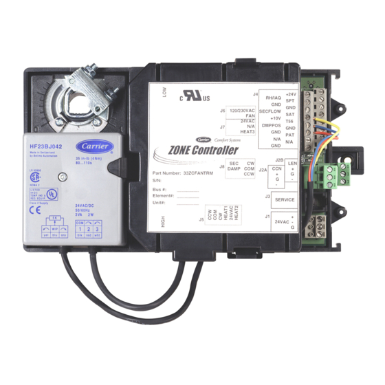
Class 2 Supply 24VAC/DC 50/60 Hz 3VA 2W 1 2 3 → Fig. 4 — Single Duct Air Terminal Zone Controller ® ZONE Controller ® Part Number: 33ZCFANTRM S/N: Bus#: Element#: Unit#: ® ZONE Controller ® Part Number: 33ZCVAVTRM S/N:... -
Page 6: Mounting
ZONE Controller H F 2 3 B J 0 4 2 M a d e i n S w i t z e r l a n d b y B e l i m o A u t o m a t i o n 35 in-lb (4 Nm) 80...110s L R 9 2 8 0 0... -
Page 7: Connect The Power Transformer
The electric heat con- tactor(s) are limited to 10 va (holding) each. For 33ZCFANTRM zone controllers, the power require- ment sizing allows for accessory water valves and for the fan contactor. Water valves are limited to 8 va on both two-position and modulating hot water. - Page 15 24V*...
-
Page 19: Install Sensors
A space temperature sensor must be installed for each zone controller. There are three types of SPT sensors available from Carrier: the 33ZCT55SPT space temperature sensor with timed override button, the 33ZCT56SPT space temperature sensor with timed override button and set point adjustment and the 33ZCT58SPT with liquid crystal display. - Page 20 NOTE: Minimum length of tubing is 2 ft. Cool Warm Fig. 10 — Space Temperature Sensor (P/N 33ZCT56SPT Shown) LOW PRESSURE TUBING H F 2 3 B J 0 4 2 M a d e i n S w i t z e r l a n d b y B e l i m o A u t o m a t i o n 35 in-lb (4 Nm) 80...110s...
- Page 21 RED(+) WHT(GND) BLK(-) BLK (GND) RED (SPT) Fig. 12 — Space Temperature Sensor Wiring (33ZCT55SPT) Table 1 — Thermistor Resistance vs Temperature Values for Space Temperature Sensor, Return-Air Temperature Sensor, and Supply-Air Temperature Sensor TEMP –40 –35 –30 –25 –20 –15 –10 –5...
- Page 22 Wiring when distance between zone controller and space temperature sensor is 100 feet or less 2 COND TWISTED CABLE OR 3 COND CABLE (TEMP SENSOR WIRING) (TYP) ZONE AIR TERMINAL CONTROLLER UNIT (TYP) (TYP) Wiring when distance between zone controller and space temperature sensor is greater than 100 feet CCN COMM BUS 2 COND TWISTED CABLE OR 3 COND...
-
Page 23: Primary Air Temperature Sensor Installation
PRIMARY AIR TEMPERATURE SENSOR INSTALLA- TION — A primary air temperature (PAT) sensor is used on a zone controller which is functioning as a Linkage Coordinator for a non CCN/Linkage compatible air source. The part num- ber is 33ZCSENPAT. See Fig. 15. When used on a zone controller, try to select a zone control- ler which will allow installation of the PAT sensor in the main trunk, as close to the air source as possible. - Page 24 PRIMARY AIR INLET PRIMARY AIR INLET ZC — Zone Controller → → → → Fig. 17 — Supply Air Temperature Probe (Part No. 33ZCSENSAT) Locations The CO sensors (33ZCSENCO2) factory set for a range of 0 to 2000 ppm and a linear voltage output of 0 to 10 vdc. Figure 19 shows ventilation rates for various CO when outside air with a typical CO level of 350 ppm is used.
-
Page 25: Installation
→ Fig. 20 — Indoor Air Quality Sensor Wiring The sensor must be mounted vertically on the wall. The Carrier logo should be oriented correctly when the sensor is properly mounted. DO NOT mount the sensor in drafty areas such as near heat-... -
Page 26: Remote Occupancy Contact
Refer to the Install the Sensors section for sensor wiring instructions. COMMUNICATION BUS WIRE SPECIFICATIONS — The Carrier Comfort Network (CCN) Communication Bus wiring is field-supplied and field-installed. It consists of shielded three-conductor cable with drain (ground) wire. The... - Page 27 3. Connect the other end of the communication bus cable to the terminal block labeled CCN in the zone control- ler of the first air terminal. Following the color code in Table 3, connect the Red (+) wire to Terminal 1. Connect the White (ground) wire to Terminal 2.
-
Page 29: Start-Up
LEGEND — Carrier Comfort Network — Zone Controller START-UP Use the Carrier network communication software to start up and configure the zone controller. All set-up and set point configurations are factory-set and field-adjustable. Changes can be made using the ComfortWORKS ware, ComfortVIEW™... -
Page 30: Network Addressing
9. Check to be sure the area around the air handler(s) is clear of construction dirt and debris. 10. Check that final filters are installed in the air han- dler(s). Dust and debris can adversely affect system operation. 11. Verify that the zone controller and the air handler con- trols are properly connected to the CCN bus. -
Page 31: Configuration
The following sections describe the computer configuration screens which are used to configure the zone controller. The screens shown may be displayed differently when using differ- ent Carrier software. Points Display Screen — The Points Display screen allows the user to view the status of the air terminal controller points. -
Page 32: Controller Identification Screen
SUPPLY AIR TEMPERATURE — Temperature of the air leaving the zone controller downstream of any ducted heat source. Measured by a 10 kΩ thermistor (Type III). This tem- perature is used to control the maximum discharge air to the space when local heat is active. The sensor is not required or recommended for cooling only terminals. -
Page 33: Controller Identification Screen
Alarm Routing Control — This decision indicates which CCN system software or devices will receive and process alarms sent by the zone controller. This decision consists of eight digits each can be set to zero or one. A setting of 1 indi- cates alarms should be sent to this device. -
Page 34: Screen
LINKAGE COORDINATOR SCREEN — The Linkage Coordinator Configuration screen allows the user to set the linkage coordinator configuration set- tings. See Table 6. Linkage Master Zone — This decision defines if the zone controller will function as a Linkage Coordinator (Linkage Master) for itself and other zones. -
Page 35: Occupancy Configuration Screen
Reset Minimum Damper Position: Units Range Default Value Reset Maximum Damper Position: Units Range Default Value Maximum Reset: Units Range Default Value Static Pressure Reset Variable Name: Units Range Default Value *To use Static Pressure Reset with a Comfort System AirManager, configure the variable name to SPRESET. -
Page 36: Set Point Screen
Table 7 — Occupancy Schedule Information Screen DESCRIPTION Manual Override Hours Period 1: Day of Week Period 1: Occupied From Period 1: Occupied To Period 2: Day of Week Period 2: Occupied From Period 2: Occupied To Period 3: Day of Week Period 3: Occupied From Period 3: Occupied To Period 4: Day of Week... -
Page 37: Service Configuration Selection Screen
Air Quality — The Air Quality set point is used to configure the IAQ set point for the zone controller if optional controlled ventilation support is used. Air Quality Units none shown (ppm (ppm): implied) Range 0 to 5000 Default Value Delta Airflow —... -
Page 38: Terminal Service Configuration Screen
The inclusion of these configuration set- tings does not indicate that Carrier is endorsing this product for pressure dependent operation. In the case of a pressure sensor failure, the zone controller will broadcast a pressure sensor failure message on the CCN bus. -
Page 39: Terminal Service Configuration Screen
The default PMF value of 2.273 is the correct value to use when the zone controller is used with a Carrier probe in a Carrier air terminal. For terminals and probes supplied by other manufacturers, the PMF must be calculated and entered into the zone controller configuration in order to correctly measure airflow. - Page 40 The calibration gain is used for the fine tuning adjustments which might need to be made to the airflow calculation. This number is calculated automatically by the zone controller after input to the air balance maintenance screen, or it can be input manually at this screen.
-
Page 41: Options Service Configuration Screen
Start Value: Units F (C) Range 40 to 125 Default Value Ducted Heat — The Ducted Heat configuration is used to con- figure the terminal for ducted heat. If a local heat source is in the duct and requires airflow to provide heat, set the Ducted Heat configuration for yes. -
Page 42: Configuration Screen
Override — The Override parameter is used to configure the number of hours and minutes the override will be in effect. The user initiates override by pressing the override button on the space temperature sensor. This will cause the schedule to enter into the Occupied mode. -
Page 43: Maintenance Table Menu Screen
The default of 2.443 is the correct value to use if the probe is a Carrier probe in a 35 or 45 Series terminal. The formula for calculating velocity using an Ideal probe is:... - Page 44 This value will be sent to all associated zones for optimum start of zone controllers. This function is supported by all Carrier equipment which perform linkage. Start Bias Time: Display Units...
- Page 45 DESCRIPTION Air Source Bus Number Air Source Element Number Master Zone Element Number Operating Mode Air Source Supply Temperature Start Bias Time Average Occupied Heat Set Point Average Occupied Cool Set Point Average Unoccupied Heat Set Point Average Unoccupied Cool Set Point Average Zone Temperature Average Occupied Zone Temperature Composite CCN Value...
- Page 46 This number is rounded to the nearest tenth of an inch and will be subtracted to the static pressure reset value unless the static pressure reset value has reached zero. Pressure Increase Value: Display Units in. wg Display Range 0.000 to 5.000 Default Value 0.000 Network Access Read/Write...
- Page 47 → Next Unoccupied Time — This variable displays the time of day when the next unoccupied period is scheduled to begin. This point is read in conjunction with the next unoccupied day to allow the user to know the next time and day when the zone will become unoccupied.
- Page 48 → Table 15 — Zone Air Balance/Commissioning Table DESCRIPTION Commissioning Mode Damper/Transducer Calibration Maximum Cooling Minimum Cooling Heating Override Fan Override CFM Set Point Actual Airflow Primary Damper Position Measured Velocity Pressure Supply Air Temperature Auto-Calibration Calibration Gain Heating Override — This variable can be used to test the heat outputs.
- Page 49 ZONE MAINTENANCE TABLE — The Zone Maintenance table is used to display zone set points and variables. See Table 16. Occupied — This variable indicates if the zone controller is operating in the occupied mode. Occupied: Display Range Default Value Network Access Read Only →...
- Page 50 Heat Master Reference — This point displays the occupied heat set point if occupied, or the unoccupied heat set point if unoccupied. This variable will display any space temperature sensor slidebar offset that is being applied. Heat Master Reference: Display Units F (C) Display Range 40.0 to 90.0...
- Page 52 Copyright 1999 Carrier Corporation Manufacturer reserves the right to discontinue, or change at any time, specifications or designs without notice and without incurring obligations. Book 1 PC 111 Catalog No. 533-355 Printed in U.S.A. Form 33ZC-1SI Pg 52 11-99 Replaces: New...
Need help?
Do you have a question about the 33ZCFANTRM and is the answer not in the manual?
Questions and answers