
Related Manuals for GEM R677


Summary of Contents for GEM R677
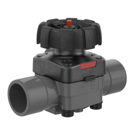
- Page 1 GEMÜ R677 Manuell betätigtes Membranventil Manually operated diaphragm valve Betriebsanleitung Operating instructions Weitere Informationen Webcode: GW-R677...
- Page 2 Alle Rechte, wie Urheberrechte oder gewerbliche Schutzrechte, werden ausdrücklich vorbehalten. All rights including copyrights or industrial property rights are expressly reserved. Dokument zum künftigen Nachschlagen aufbewahren. Keep the document for future reference. © GEMÜ Gebr. Müller Apparatebau GmbH & Co. KG 05.10.2023 GEMÜ R677 2 / 64...
-
Page 3: Table Of Contents
15.1 Antrieb demontieren ........15.2 Membran demontieren ......... 15.3 Membran montieren ........15.4 Antrieb montieren .......... 15.5 Schnittbild und Ersatzteile ......16 Entsorgung ............17 Rücksendung ............18 Original EU-Konformitätserklärung gemäß 2014/68/EU (Druckgeräterichtlinie) ..... www.gemu-group.com 3 / 64 GEMÜ R677... -
Page 4: Allgemeines
Reaktion(en) auf Tätigkeiten – Aufzählungen Symbol Bedeutung Explosionsgefahr! 1.3 Begriffsbestimmungen Betriebsmedium Medium, das durch das GEMÜ Produkt fließt. Aggressive Chemikalien! Membrangröße Einheitliche Sitzgröße der GEMÜ Membranventile für unter- schiedliche Nennweiten. Heiße Anlagenteile! 1.4 Warnhinweise Warnhinweise sind, soweit möglich, nach folgendem Schema gegliedert: Heißes Handrad während Betrieb! -
Page 5: Sicherheitshinweise
Bei Unklarheiten: steuert ein durchfließendes Medium, indem es durch den An- 15. Bei nächstgelegener GEMÜ Verkaufsniederlassung nach- wender geschlossen oder geöffnet werden kann. Ventilkörper fragen. und Membrane sind gemäß Datenblatt in verschiedenen Aus- führungen erhältlich. www.gemu-group.com 5 / 64 GEMÜ R677... -
Page 6: Bestimmungsgemäße Verwendung
Das Produkt ist für den Einbau in Rohrleitungen und zur Steue- rung eines Betriebsmediums konzipiert. Das Produkt ist bestimmungsgemäß nicht für den Einsatz in explosionsgefährdeten Bereichen geeignet. ● Das Produkt gemäß den technischen Daten einsetzen. GEMÜ R677 6 / 64 www.gemu-group.com... -
Page 7: Bestelldaten
Baulänge FTF EN 558 Reihe 1, ISO 5752, basic series 1, Baulänge nur bei Gehäuseform D 10 CONEXO Code ohne 5 Werkstoff Ventilkörper Code integrierter RFID-Chip zur elektronischen Identifizierung PVC-U, grau und Rückverfolgbarkeit PP, verstärkt PVDF www.gemu-group.com 7 / 64 GEMÜ R677... -
Page 8: Bestellbeispiel
Armaturenverschraubung mit Einlegeteil (Muffe) - DIN 5 Werkstoff Ventilkörper PVC-U, grau 6 Membranwerkstoff EPDM 7 Steuerfunktion Manuell betätigt 8 Antriebsausführung Antriebsgröße EDZ 9 Sonderausführung NSF 61 Wasser-Zulassung 10 CONEXO integrierter RFID-Chip zur elektronischen Identifizierung und Rückver- folgbarkeit GEMÜ R677 8 / 64 www.gemu-group.com... -
Page 9: Technische Daten
10,0 10,0 10,0 10,0 10,0 10,0 Erweiterte Temperaturbereiche auf Anfrage. Bitte beachten Sie, dass sich aufgrund der Umgebungs- und Medi- entemperatur eine Mischtemperatur am Ventilkörper einstellt, welche die oben angegebenen Werte nicht über- schreiten darf. www.gemu-group.com 9 / 64 GEMÜ R677... -
Page 10: Produktkonformitäten
120,0 189,0 MG = Membrangröße, Kv-Werte in m³/h Kv-Werte ermittelt gemäß DIN EN 60534, Eingangsdruck 5 bar, Δp 1 bar, Ventilkörperwerkstoff PVC-U mit Wei- chelastomermembrane. Die Kv-Werte für andere Produktkonfigurationen (z. B. andere Membran- oder Körperwerkstoffe) können abwei- chen. Im allgemeinen unterliegen alle Membranen den Einflüssen von Druck, Temperatur, des Prozesses und den Drehmomenten mit denen diese angezogen werden. -
Page 11: Mechanische Daten
1,89 0,50 0,40 0,73 0,83 0,93 1,13 2,36 0,57 0,47 1,00 1,40 1,50 1,60 3,08 0,92 3,57 3,20 4,00 3,30 6,70 4,40 4,00 8,20 MG = Membrangröße Gewichte in kg Einbaulage: beliebig Durchflussrichtung: beliebig www.gemu-group.com 11 / 64 GEMÜ R677... -
Page 12: Abmessungen
79,0 87,0 40 - 50 114,0 99,0 101,0 140,0 119,0 122,0 214,0 167,0 169,0 214,0 216,0 211,0 Maße in mm * nur bei Steuerfunktion Code L * CT = A + H1 (siehe Körpermaße) GEMÜ R677 12 / 64 www.gemu-group.com... -
Page 13: Körpermaße
Code 30: Stutzen - Zoll, zum Schweißen oder Kleben, abhängig vom Körperwerkstoff 2) Werkstoff Ventilkörper Code 1: PVC-U, grau Code 4: ABS Code 5: PP, verstärkt Code 20: PVDF Code 71: Inliner PP-H, grau, Outliner PP, verstärkt Code 75: Inliner PVDF/Outliner PP, verstärkt www.gemu-group.com 13 / 64 GEMÜ R677... - Page 14 340,0 Maße in mm MG = Membrangröße 1) Anschlussart Code 20: Stutzen zum IR-Stumpfschweißen 2) Werkstoff Ventilkörper Code 20: PVDF Code 71: Inliner PP-H, grau, Outliner PP, verstärkt Code 75: Inliner PVDF/Outliner PP, verstärkt GEMÜ R677 14 / 64 www.gemu-group.com...
- Page 15 1) Anschlussart Code 7: Armaturenverschraubung mit Einlegeteil (Muffe) - DIN 2) Werkstoff Ventilkörper Code 1: PVC-U, grau Code 4: ABS Code 71: Inliner PP-H, grau, Outliner PP, verstärkt Code 75: Inliner PVDF/Outliner PP, verstärkt www.gemu-group.com 15 / 64 GEMÜ R677...
- Page 16 Code 33: Armaturenverschraubung mit Einlegeteil Zoll - BS (Muffe) Code 3M: Armaturenverschraubung mit Einlegeteil Zoll - ASTM (Muffe) Code 3T: Armaturenverschraubung mit Einlegeteil JIS (Muffe) 2) Werkstoff Ventilkörper Code 1: PVC-U, grau Code 4: ABS GEMÜ R677 16 / 64 www.gemu-group.com...
- Page 17 G 2¾ Maße in mm MG = Membrangröße 1) Anschlussart Code 78: Armaturenverschraubung mit Einlegeteil (IR-Stumpfschweißen) - DIN 2) Werkstoff Ventilkörper Code 71: Inliner PP-H, grau, Outliner PP, verstärkt Code 75: Inliner PVDF/Outliner PP, verstärkt www.gemu-group.com 17 / 64 GEMÜ R677...
- Page 18 G 2¼ 1½ 2" 103,0 63,2 23,2 184,0 266,0 G 2¾ Maße in mm MG = Membrangröße 1) Anschlussart Code 7R: Armaturenverschraubung mit Einlegeteil (Gewindemuffe Rp) - DIN 2) Werkstoff Ventilkörper Code 1: PVC-U, grau GEMÜ R677 18 / 64 www.gemu-group.com...
- Page 19 Code 4: Flansch EN 1092, PN 10, Form B, Baulänge FTF EN 558 Reihe 1, ISO 5752, basic series 1 2) Werkstoff Ventilkörper Code 1: PVC-U, grau Code 5: PP, verstärkt Code 20: PVDF www.gemu-group.com 19 / 64 GEMÜ R677...
- Page 20 Code 4: Flansch EN 1092, PN 10, Form B, Baulänge FTF EN 558 Reihe 1, ISO 5752, basic series 1 2) Werkstoff Ventilkörper Code 71: Inliner PP-H, grau, Outliner PP, verstärkt Code 75: Inliner PVDF/Outliner PP, verstärkt GEMÜ R677 20 / 64 www.gemu-group.com...
- Page 21 Code 39: Flansch ANSI Class 125/150 RF, Baulänge FTF EN 558 Reihe 1, ISO 5752, basic series 1, Baulänge nur bei Gehäuseform D 2) Werkstoff Ventilkörper Code 1: PVC-U, grau Code 5: PP, verstärkt Code 20: PVDF www.gemu-group.com 21 / 64 GEMÜ R677...
- Page 22 Code 39: Flansch ANSI Class 125/150 RF, Baulänge FTF EN 558 Reihe 1, ISO 5752, basic series 1, Baulänge nur bei Gehäuseform D 2) Werkstoff Ventilkörper Code 71: Inliner PP-H, grau, Outliner PP, verstärkt Code 75: Inliner PVDF/Outliner PP, verstärkt GEMÜ R677 22 / 64 www.gemu-group.com...
-
Page 23: Ventilkörperbefestigung
25,0 M6 * 25,0 40 - 50 M8 * 44,5 M8 * 44,5 1/2“ ** 100,0 3/4“ ** 120,0 Maße in mm, MG = Membrangröße * Zollgewinde auf Anfrage ** Metrisches Gewinde auf Anfrage www.gemu-group.com 23 / 64 GEMÜ R677... -
Page 24: Lieferung
3. Maximale Lagertemperatur nicht überschreiten (siehe Ka- Nur an abgekühlter Anlage arbeiten. ● pitel „Technische Daten“). 4. Lösungsmittel, Chemikalien, Säuren, Kraftstoffe u. ä. nicht mit GEMÜ Produkten und deren Ersatzteilen in einem VORSICHT Raum lagern. Überschreitung des maximal zulässigen Drucks! ▶ Beschädigung des Produkts Schutzmaßnahmen gegen Überschreitung des maximal... -
Page 25: Einbau Mit Schweißstutzen
Verbrühungen ausgeschlossen sind. 9. Überwurfmutter wieder auf GEMÜ R677 Körper schrauben. 11. Anlage bzw. Anlagenteil fachgerecht dekontaminieren, 10. GEMÜ R677 Körper an anderer Seite ebenfalls mit Rohrlei- spülen und belüften. tung verbinden. 12. Rohrleitungen so legen, dass Schub- und Biegungskräfte, 11. -
Page 26: Einbau Mit Klebestutzen
Fremdstoffe). Abb. 4: Klebestutzen VORSICHT HINWEIS Reinigungsmedium! ▶ Der Klebstoff ist nicht im Lieferumfang enthalten. ▶ Beschädigung des GEMÜ Produkts. Nur geeigneten Klebstoff verwenden! ● Der Betreiber der Anlage ist verantwortlich für die Aus- ● 1. Montagevorbereitungen durchführen (siehe Kapitel „Mon- wahl des Reinigungsmediums und die Durchführung des... -
Page 27: Bedienung
Handrad nur mit Schutzhandschuhen ● betätigen. Optische Stellungsanzeige Ventil offen Ventil geschlossen Handradarretierung GEMÜ 677 (optional) Handrad abschließen: Schlüssel in Schloss (Pfeil) stecken, herunter drücken und mit Linksdrehung verriegeln. Der Schlüssel ist abziehbar. Handrad aufschließen: Schlüssel in Schloss (Pfeil) stecken und mit Rechtsdrehung entriegeln. -
Page 28: Fehlerbehebung
Gewindeanschlüsse / Verschraubungen Gewindeanschlüsse / Verschraubungen lose festziehen Dichtmittel defekt Dichtmittel ersetzen Ventilkörper des GEMÜ Produkts undicht Ventilkörper des GEMÜ Produkts defekt Ventilkörper des GEMÜ Produkts auf Be- oder korrodiert schädigungen prüfen, ggf. Ventilkörper austauschen Handrad lässt sich nicht drehen... -
Page 29: Inspektion Und Wartung
Regelwerken und Bestimmungen festlegen und regel- mäßig durchführen. 6. Teile auf Beschädigung prüfen, ggf. auswechseln (nur Ori- ginalteile von GEMÜ verwenden). HINWEIS 15.2 Membran demontieren ▶ Ist die Membrane nicht weit genug in das Verbindungs- 1. Antrieb A demontieren (siehe Kapitel „Antrieb demontie- stück eingeschraubt, wirkt die Schließkraft direkt auf den... -
Page 30: Antrieb Montieren
übereinstimmt. brane) muss das PTFE-Membranschild und die EPDM- 7. Steg von Druckstück und Membrane parallel ausrichten. Stützmembrane plan und parallel am Ventilkörper an- liegen. 8. Komplett montiertes Ventil auf Funktion und Dichtheit prü- fen. GEMÜ R677 30 / 64 www.gemu-group.com... -
Page 31: Schnittbild Und Ersatzteile
Produkt keine Rücksendeerklärung bei, erfolgt keine Gut- für Rückmelder schrift bzw. keine Erledigung der Reparatur, sondern eine kos- tenpflichtige Entsorgung. 1. Das Produkt reinigen. 2. Rücksendeerklärung bei GEMÜ anfordern. 3. Rücksendeerklärung vollständig ausfüllen. 4. Das Produkt mit ausgefüllter Rücksendeerklärung an GEMÜ schicken. Pos. -
Page 32: Original Eu-Konformitätserklärung Gemäß 2014/68/Eu (Druckgeräterichtlinie)
Hinweis für Produkte mit einer Nennweite ≤ DN 25: Die Produkte werden entwickelt und produziert nach GEMÜ eigenen Verfahrensanweisungen und Qualitätsstandards, welche die Forderungen der ISO 9001 und der ISO 14001 erfüllen. Die Produkte dürfen gemäß Artikel 4, Absatz 3 der Druckgeräterichtlinie 2014/68/EU keine CE-Kennzeichnung tragen. - Page 33 Mounting the diaphragm ......15.4 Mounting the actuator ........15.5 Sectional drawing and spare parts ....16 Disposal .............. 17 Returns ..............18 EU Declaration of Conformity in accordance with 2014/68/EU (Pressure Equipment Directive) ..www.gemu-group.com 33 / 64 GEMÜ R677...
-
Page 34: General Information
Hot plant components! Working medium The medium that flows through the GEMÜ product. Diaphragm size Uniform seat size of GEMÜ diaphragm valves for different Handwheel can become hot during operation! nominal sizes. 1.4 Warning notes Wherever possible, warning notes are organised according to... -
Page 35: Safety Information
(see Conexo information) 3.2 Function In cases of uncertainty: 15. Consult the nearest GEMÜ sales office. The product is designed for use in piping. It controls a flowing medium by manual operation. The valve body and the dia- phragm are available in various designs as shown in the data- sheet. -
Page 36: Correct Use
The product is designed for installation in piping systems and for controlling a working medium. The product is not intended for use in potentially explosive areas. ● Use the product in accordance with the technical data. GEMÜ R677 36 / 64 www.gemu-group.com... -
Page 37: Order Data
Integrated RFID chip for electronic identification and length only for body configuration D traceability 5 Valve body material Code PVC-U, grey PP, reinforced PVDF Inliner PP-H, grey, outliner PP, reinforced Inliner PVDF/outliner PP, reinforced www.gemu-group.com 37 / 64 GEMÜ R677... -
Page 38: Order Example
6 Diaphragm material EPDM 7 Control function Manually operated 8 Actuator version Actuator size EDZ (diaphragm size 20) 9 Special version NSF 61 water approval 10 CONEXO Integrated RFID chip for electronic identification and traceability GEMÜ R677 38 / 64 www.gemu-group.com... -
Page 39: Technical Data
10,0 10,0 10,0 10,0 10,0 10,0 Data for extended temperature ranges on request. Please note that the ambient temperature and media temper- ature generate a combined temperature at the valve body which must not exceed the above values. www.gemu-group.com 39 / 64 GEMÜ R677... -
Page 40: Product Conformity
6.4 Product conformity Pressure Equipment Dir- 2014/68/EU ective: Food: FDA* Regulation (EC) No. 1935/2004 Regulation (EC) No. 10/2011* EAC: TR CU 010/2011 Drinking water: NSF/ANSI* * depending on version and / or operating parameters GEMÜ R677 40 / 64 www.gemu-group.com... -
Page 41: Mechanical Data
0.73 0.83 0.93 1.13 2.36 0.57 0.47 1.00 1.40 1.50 1.60 3.08 0.92 3.57 3.20 4.00 3.30 6.70 4.40 4.00 8.20 MG = diaphragm size Weights in kg Installation position: Optional Flow direction: Optional www.gemu-group.com 41 / 64 GEMÜ R677... -
Page 42: Dimensions
40 - 50 114.0 99.0 101.0 140.0 119.0 122.0 214.0 167.0 169.0 214.0 216.0 211.0 * only for control function code L * CT = A + H1 (see body dimensions) Dimensions in mm GEMÜ R677 42 / 64 www.gemu-group.com... -
Page 43: Body Dimensions
Code 30: Spigot - inch, for welding or solvent cementing, dependent on body material 2) Valve body material Code 1: PVC-U, grey Code 4: ABS Code 5: PP, reinforced Code 20: PVDF Code 71: Inliner PP-H, grey, outliner PP, reinforced Code 75: Inliner PVDF/outliner PP, reinforced www.gemu-group.com 43 / 64 GEMÜ R677... - Page 44 MG = diaphragm size 1) Connection type Code 20: Spigot for IR butt welding 2) Valve body material Code 20: PVDF Code 71: Inliner PP-H, grey, outliner PP, reinforced Code 75: Inliner PVDF/outliner PP, reinforced GEMÜ R677 44 / 64 www.gemu-group.com...
- Page 45 Code 7: Union end with insert (socket) – DIN 2) Valve body material Code 1: PVC-U, grey Code 4: ABS Code 71: Inliner PP-H, grey, outliner PP, reinforced Code 75: Inliner PVDF/outliner PP, reinforced www.gemu-group.com 45 / 64 GEMÜ R677...
- Page 46 Code 33: Union end with inch insert - BS (socket) Code 3M: Union end with inch insert – ASTM (socket) Code 3T: Union end with JIS insert (socket) 2) Valve body material Code 1: PVC-U, grey Code 4: ABS GEMÜ R677 46 / 64 www.gemu-group.com...
- Page 47 MG = diaphragm size 1) Connection type Code 78: Union end with insert (for IR butt welding) – DIN 2) Valve body material Code 71: Inliner PP-H, grey, outliner PP, reinforced Code 75: Inliner PVDF/outliner PP, reinforced www.gemu-group.com 47 / 64 GEMÜ R677...
- Page 48 23.2 184.0 266.0 G 2¾ Dimensions in mm MG = diaphragm size 1) Connection type Code 7R: Union end with insert (Rp threaded socket) - DIN 2) Valve body material Code 1: PVC-U, grey GEMÜ R677 48 / 64 www.gemu-group.com...
- Page 49 Code 4: Flange EN 1092, PN 10, form B, face-to-face dimension FTF EN 558 series 1, ISO 5752, basic series 1 2) Valve body material Code 1: PVC-U, grey Code 5: PP, reinforced Code 20: PVDF www.gemu-group.com 49 / 64 GEMÜ R677...
- Page 50 Code 4: Flange EN 1092, PN 10, form B, face-to-face dimension FTF EN 558 series 1, ISO 5752, basic series 1 2) Valve body material Code 71: Inliner PP-H, grey, outliner PP, reinforced Code 75: Inliner PVDF/outliner PP, reinforced GEMÜ R677 50 / 64 www.gemu-group.com...
- Page 51 Code 39: Flange ANSI Class 125/150 RF, face-to-face dimension FTF EN 558 series 1, ISO 5752, basic series 1, length only for body config- uration D 2) Valve body material Code 1: PVC-U, grey Code 5: PP, reinforced Code 20: PVDF www.gemu-group.com 51 / 64 GEMÜ R677...
- Page 52 Code 39: Flange ANSI Class 125/150 RF, face-to-face dimension FTF EN 558 series 1, ISO 5752, basic series 1, length only for body config- uration D 2) Valve body material Code 71: Inliner PP-H, grey, outliner PP, reinforced Code 75: Inliner PVDF/outliner PP, reinforced GEMÜ R677 52 / 64 www.gemu-group.com...
-
Page 53: Valve Body Mounting
M6 * 25.0 40 - 50 M8 * 44.5 M8 * 44.5 1/2“ ** 100.0 3/4“ ** 120.0 Dimensions in mm, MG = diaphragm size * Inch thread on request ** Metric thread on request www.gemu-group.com 53 / 64 GEMÜ R677... -
Page 54: Delivery
Only work on plant that has cooled ● chapter "Technical data"). down. 4. Do not store solvents, chemicals, acids, fuels or similar fluids in the same room as GEMÜ products and their spare CAUTION parts. Exceeding the maximum permissible pressure! ▶ Damage to the product Provide precautionary measures against exceeding the ●... -
Page 55: Installation With Butt Weld Spigots
9. Screw the union nut back onto the GEMÜ R677 body. verse and bending forces, and also from vibrations and tension. 10. Connect the GEMÜ R677 body to the piping on the other side in a like manner. 13. Only install the product between matching aligned pipes (see chapters below). -
Page 56: Installation With Solvent Cement Spigots
Fig. 4: Solvent cement spigot CAUTION NOTICE Cleaning agent ▶ The solvent cement is not included in the scope of deliv- ▶ Damage to the GEMÜ product. ery. The plant operator is responsible for selecting the clean- Only use suitable solvent cement! ●... -
Page 57: Operation
Optical position indicator Valve open Valve closed Handwheel locknut GEMÜ 677 (optional) Lock the handwheel: Insert the key in the lock (arrow), press down and lock with an anticlockwise rotation. The key can be removed. Unlock the handwheel: Insert the key in the lock (arrow) and unlock with a clockwise rotation. -
Page 58: Troubleshooting
Threaded connections / unions loose Tighten threaded connections / unions Sealing material faulty Replace sealing material Valve body of the GEMÜ product is leak- Valve body of the GEMÜ product is faulty Check valve body of the GEMÜ product or corroded... -
Page 59: Inspection And Maintenance
6. Check parts for potential damage, replace if necessary NOTICE (only use genuine parts from GEMÜ). ▶ If the diaphragm is not screwed into the adapter far 15.2 Removing the diaphragm enough, the closing force is transmitted directly onto the 1. -
Page 60: Mounting The Actuator
7. Align the weir of compressor and diaphragm in parallel. parallel to the valve body. 8. With the valve fully assembled, check the function and tightness. GEMÜ R677 60 / 64 www.gemu-group.com... -
Page 61: Sectional Drawing And Spare Parts
Connection thread goods can be processed only when this note is completed. If for position no return delivery note is included with the product, GEMÜ indicator cannot process credits or repair work but will dispose of the goods at the operator's expense. -
Page 62: Eu Declaration Of Conformity In Accordance With 2014/68/Eu (Pressure Equipment Directive)
Information for products with a nominal size ≤ DN 25: The products are developed and produced according to GEMÜ's in-house process instructions and standards of quality which comply with the requirements of ISO 9001 and ISO 14001. According to Article 4, Paragraph 3 of the Pressure Equipment Direct- ive 2014/68/EU, these products must not be identified by a CE-marking. - Page 63 GEMÜ R677 63 / 64 www.gemu-group.com...
- Page 64 GEMÜ Gebr. Müller Apparatebau GmbH & Co. KG Fritz-Müller-Straße 6-8, 74653 Ingelfingen-Criesbach, Germany Änderungen vorbehalten Phone +49 (0) 7940 1230 · info@gemue.de Subject to alteration www.gemu-group.com 10.2023 | 88364606...
Need help?
Do you have a question about the R677 and is the answer not in the manual?
Questions and answers