Table of Contents
Advertisement
Quick Links
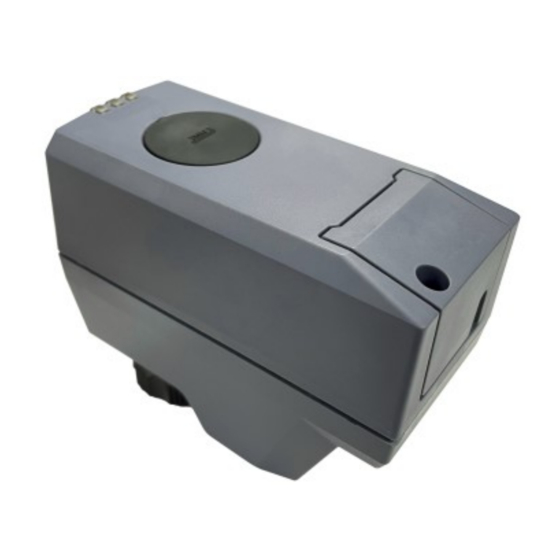
Electromotoric actuator
SSE161.05U, SSF161.05U
A6V12681514_enUS_b
06/15/2023
For 2-way & 3-way 599 Series Zone Valves
●
Operating voltage AC/DC 24 V, positioning signal DC 0...10 V
●
Self-calibrating to the valve stroke
●
Direct mounting with coupling nut, no tools required
●
Manual override
●
Position and actuator motion indication (LED)
●
Positioning force 45 lbf (200 N)
●
Parallel operation of multiple actuators possible
●
3-pin terminal block
Smart Infrastructure
Advertisement
Table of Contents

Related Manuals for Siemens SSE161.05U


Summary of Contents for Siemens SSE161.05U
- Page 1 Electromotoric actuator SSE161.05U, SSF161.05U For 2-way & 3-way 599 Series Zone Valves ● Operating voltage AC/DC 24 V, positioning signal DC 0...10 V ● Self-calibrating to the valve stroke ● Direct mounting with coupling nut, no tools required ● Manual override ●...
-
Page 2: Technical Design
● Typically in chilled ceiling, VAV and fan coil unit applications ● Max.10 units of SSE161.05U, SSF161.05U can operate in parallel, provided the controller output suffices. Technical design When the actuator is driven by DC 0…10 V positioning signal, it produces a stroke, which is transmitted to the valve stem. -
Page 3: Type Summary
Valves and actuators can be ordered assembled in the factory or ordered separately. For easier valve assembly, actuators ordered separately have the actuator stem fully retracted. Equipment combinations Valves Combinable valves for SSE161.05U and SSF161.05U - 2-way & 3-way 599 Series Zone Valve Nominal Line Size Flow Rate... -
Page 4: Product Documentation
Environmental compatibility Environmental declarations A5W00242127A Related documents such as the environmental declarations, declarations of conformity, etc., can be downloaded from the following Internet address: www.siemens.com/bt/download Notes Engineering The actuators must be electrically connected in accordance with local regulations (see "Connection diagrams”). -
Page 5: Self-Calibration
● After three failed calibration attempts, the actuator stem remains in the extended position and the valves are open. Manual operation A 3-mm hexagonal wrench can be used to move the actuator to any position. Siemens A6V12681514_enUS_b Smart Infrastructure 06/15/2023... - Page 6 (a). Cabling operation 1. Unscrew cover screw 2. Remove cover 3. Connect or disconnect wire terminals (terminal block is removable) 4. Install the cover 5. Screw in the cover screw Siemens A6V12681514_enUS_b Smart Infrastructure 06/15/2023...
-
Page 7: Maintenance
Comply with all local and currently applicable laws and regulations. Warranty Technical data on specific applications are valid only together with Siemens products listed under "Equipment combinations". Siemens rejects any and all warranties in the event that third-party products are used. -
Page 8: Technical Data
Plastic coupling nut M30 × 1.5 Orientation Above horizontal Standards EU conformity declaration (CE) A5W00254962A RCM conformity declaration A5W00254983A UK conformity declaration (UKCA) A5W00257055A Housing protection degree NEMA 2 / IP20 (EN 60529) Protection class according to EN 60730 Siemens A6V12681514_enUS_b Smart Infrastructure 06/15/2023... - Page 9 -13 to 158° F (-25…70 ℃) Humidity 5…95 % r.h. < 95 % r.h. 5…95 % r.h. non condensing non condensing non condensing Atmospheric Min. 700 hPa, corresponding to pressure max. 3,000 m above sea level Siemens A6V12681514_enUS_b Smart Infrastructure 06/15/2023...
- Page 10 Material Cover/base PC + ABS Weight SSE161.05U 7.7 ounces (217 g) SSF161.05U 7.6 ounces (216 g) Siemens A6V12681514_enUS_b Smart Infrastructure 06/15/2023...
-
Page 11: Connection Terminals
Control signal DC 0...10 V System potential (AC/DC 24 V) Connection diagrams N = Controller Y = Actuator SP, G = System potential AC 24 V SN, G0 = System neutral Y = Control signal SN (-) Siemens A6V12681514_enUS_b Smart Infrastructure 06/15/2023... -
Page 12: Revision Numbers
Dimensions mm (inch) 76.7 27.7 (3") (1.1") (1.9") Revision numbers Type Valid from rev. no. SSE161.05U SSF161.05U Siemens A6V12681514_enUS_b Smart Infrastructure 06/15/2023... - Page 14 Issued by © Siemens 2023 Siemens Switzerland Ltd Technical specifications and availability subject to change without notice. Smart Infrastructure Global Headquarters Theilerstrasse 1a CH-6300 Zug +41 58 724 2424 www.siemens.com/buildingtechnologies Document ID A6V12681514_enUS_b Edition 06/15/2023...
Need help?
Do you have a question about the SSE161.05U and is the answer not in the manual?
Questions and answers