Advertisement
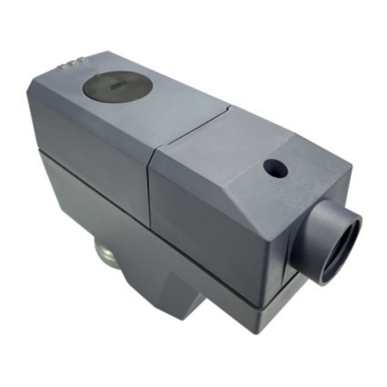
Electromotoric actuator
SSC161.05U, SSC161.35U, SSC131.39U
A6V12681517_enUS_a
02/09/2023
For Powermite MT Series 2-way and 3-way globe valves
●
SSC161.05U (fail-in-place), and SSC161.35U (fail-safe): Operating voltage AC/DC
24 V, modulating control signal DC 0...10 V
●
SSC131.39U (fail-safe): Operating voltage AC 24 V, 3-position (floating) control
signal
●
All actuators are self-calibrating to the valve stroke
●
Modulating variants have position feedback signal
●
Direct mounting with coupling nut, no tools required
●
Manual override
●
Position and actuator motion indication (LED)
●
Positioning force 67 lbf (300 N)
●
Parallel operation of multiple actuators possible
Smart Infrastructure
Advertisement
Table of Contents

Related Manuals for Siemens SSC161.35U


Summarization of Contents
Technical design
3-position control signal (for SSC131.39U only)
Details control signal for SSC131.39U, voltage inputs, and stem movement.
DC 0...10 V control signal
Explains proportional control signal and feedback for modulating actuators, includes graph.
LED indication
LED indication patterns
Describes LED states (flashing, constant) for various operational statuses.
Notes
Engineering
Specifies electrical connection requirements and compliance with local regulations.
National safety regulations
Warns about potential injury and damage from non-compliance with safety regulations.
Mounting
Provides warnings and instructions for safely mounting the actuator without damage.
Orientation
Describes the correct physical orientation of the actuator during installation.
Commissioning
Outlines checks for wiring and actuator functioning during commissioning.
Self-calibration
Electrical fail-safe function (for SSC161.35U, SSC131.39U only)
Explains fail-safe mechanism, capacitor charging, and response during power failures.
Manual operation
Details how to manually move the actuator stem using an Allen wrench and button.
Open Source Software (OSS)
Software license overview
Provides info on Open Source Software components used in the product and their availability.
Technical data
Power supply
Lists operating voltage, frequency, power consumption, and fuse/breaker ratings.
Signal input
Details control signal types (modulating, floating) and input impedance.
Signal output
Describes feedback signal characteristics, including max output current and resolution.
Operating data
Covers position with de-energized contact, running speed, positioning force, and temperature limits.
Diagrams
Connection terminals
Illustrates and labels the connection terminals for different actuator models.
Dimensions
Revision numbers
Lists actuator types and the revision numbers from which they are valid.
Need help?
Do you have a question about the SSC161.35U and is the answer not in the manual?
Questions and answers