Table of Contents
Advertisement
Quick Links
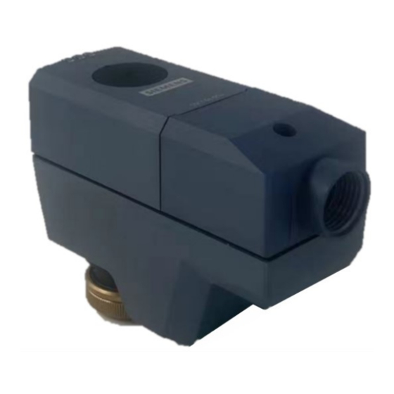
Electromotoric actuator
SSC161.05UT
A6V13359035_en--_b
2023-05-16
For pressure independent zone valves, small globe valves and 3-party valves
●
Operating voltage AC/DC 24 V, positioning signal DC 0...10 V
●
Self calibrating to the valve stroke
●
Direct mounting with coupling nut, no tools required
●
Manually override
●
Position and actuator motion indication (LED)
●
Positioning force 300 N
●
Parallel operation of multiple actuators possible
Smart Infrastructure
Advertisement
Table of Contents

Subscribe to Our Youtube Channel
Related Manuals for Siemens SSC161.05UT


Summary of Contents for Siemens SSC161.05UT
- Page 1 Electromotoric actuator SSC161.05UT For pressure independent zone valves, small globe valves and 3-party valves ● Operating voltage AC/DC 24 V, positioning signal DC 0...10 V ● Self calibrating to the valve stroke ● Direct mounting with coupling nut, no tools required ●...
-
Page 2: Technical Design
● For zone valves VVP.., VXP.., VMP..: compatible with SSC161.05UT ● For 2-/3-port valves: compatible with SSC161.05UT ● Typically in chilled ceiling, VAV and fan coil unit applications ● Max.10 units of SC161.05UT can operate in parallel, provided the controller output suffices. - Page 3 When ordering, specify both type and quantity. Example: Type Stock number Designation Quantity SSC161.05UT S55180-A149 Electromotoric actuator Delivery Valves and actuators must be ordered separately. For easier valve assembly, actuators ordered separately have the actuator stem fully retracted. Equipment combinations...
- Page 4 Environmental compatibility Environmental declarations A5W00244689A Related documents such as the environmental declarations, declarations of conformity, etc., can be downloaded from the following Internet address: www.siemens.com/bt/download Notes Engineering The actuators must be electrically connected in accordance with local regulations (see "Connection diagram [▶...
-
Page 5: Installation
Actuator stem retracts Normally open valve opens, normally closed valve closes NOTICE The actuator must be commissioned only with a correctly mounted valve in place! Self-calibration When operating voltage is applied, the actuator self-calibrates (fully retracted ➙ fully extended ➙ setpoint). Siemens A6V13359035_en--_b Smart Infrastructure 2023-05-16... - Page 6 ● If calibration fails, the actuator performs another calibration automatically after 10 seconds. ● After three failed calibration attempts, the actuator stem remains in the extended position and the valves are open. Siemens A6V13359035_en--_b Smart Infrastructure 2023-05-16...
- Page 7 (a). Cabling operation 1. Unscrew cover screw 2. Remove cover 3. Connect or disconnect wire terminals 4. Install the cover 5. Screw in the cover screw Siemens A6V13359035_en--_b Smart Infrastructure 2023-05-16...
-
Page 8: Maintenance
Comply with all local and currently applicable laws and regulations. Warranty Technical data on specific applications are valid only together with Siemens products listed under "Equipment combinations". Siemens rejects any and all warranties in the event that third-party products are used. - Page 9 Firmware version OSS document Device Document ID Title 2.10.0 or above A6V13503690 Readme OSS for Modulating Room Actuator 200N, 300N Siemens A6V13359035_en--_b Smart Infrastructure 2023-05-16...
-
Page 10: Technical Data
1…120 °C valve Electrical connection (connecting cable integral) Permissible length for signal lines <20 m Wire cross section 0.5...0.75 mm² Cable diameter <5.5 mm Mounting Connection to valve Brass coupling nut ¾” inch Orientation 360° Siemens A6V13359035_en--_b Smart Infrastructure 2023-05-16... -
Page 11: Fcc Regulations
(1) This device may not cause harmful interference, and (2) this device must accept any interference received, including interference that may cause undesired operation. Housing color Cover/base 2003, Ti-Gray Coupling nut Metal General ambient conditions Operation Transport Storage Siemens A6V13359035_en--_b Smart Infrastructure 2023-05-16... - Page 12 5…95 % r.h. <95 % r.h. 5…95 % r.h. non condensing non condensing non condensing Atmospheric Min. 700 hPa, corresponding to pressure max. 3,000 m above sea level Material Cover/base PC + ABS Weight 280 g Siemens A6V13359035_en--_b Smart Infrastructure 2023-05-16...
-
Page 13: Connection Terminals
Measurement reference Connection diagram N = Controller SP, G = System potential AC 24 V SN, G0 = System neutral Y = Positioning signal (U) (M) U = Feedback signal M = Measurement reference SN (-) Siemens A6V13359035_en--_b Smart Infrastructure 2023-05-16... -
Page 14: Revision Numbers
Dimensions 28.2 Revision numbers Type Valid from rev. no. SSC161.05UT Siemens A6V13359035_en--_b Smart Infrastructure 2023-05-16... - Page 16 Issued by © Siemens 2023 Siemens Switzerland Ltd Technical specifications and availability subject to change without notice. Smart Infrastructure Global Headquarters Theilerstrasse 1a CH-6300 Zug +41 58 724 2424 www.siemens.com/buildingtechnologies Document ID A6V13359035_en--_b Edition 2023-05-16...
Need help?
Do you have a question about the SSC161.05UT and is the answer not in the manual?
Questions and answers