Siemens SSB Series Manual
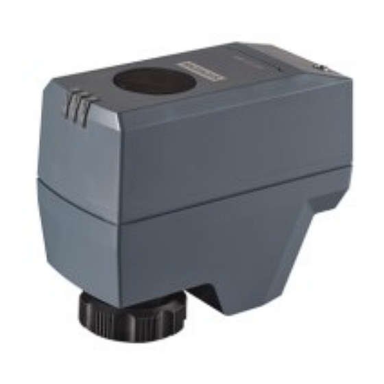
Electromotoric actuator
Hide thumbs
Also See for SSB Series:
- Mounting instructions (4 pages) ,
- Mounting instructions (4 pages) ,
- Manual (20 pages)
Table of Contents
Advertisement
Quick Links
Electromotoric actuator
SSB..
A6V15348908_en--_a
2024-06-11
For globe/control valves VVP45.., VXP45.., VMP45.. in zone and room
applications
●
SSB131.09.. operating voltage AC 24 V, 3-position control signal
●
SSB331.09.. operating voltage AC 230 V, 3-position control signal
●
SSB161.05.. Operating voltage AC/DC 24 V, positioning signal DC 0...10 V
●
Nominal force 200 N
●
Automatic identification of valve stroke
●
Direct mounting with ¾" plastic threaded coupling nut, no tools required
●
Manual override
●
Position and actuator motion indication (LED)
●
Parallel operation of multiple actuators possible
●
SSB..H integrated removable 1.5 m cable length
●
SSB..H/00 with no cable and cover for direct cable kit plug-in connection
– Accessories: PVC and halogen-free 1.5m, 3m and 6m cable length kits
●
SSB..UT 3-pin terminal block with M16x1.5 threaded integrated conduit adapter
cover, no cable
●
Load-dependent switch-off in the event of overload and in stroke end positions
Smart Infrastructure
Advertisement
Table of Contents

Subscribe to Our Youtube Channel
Related Manuals for Siemens SSB Series


Summary of Contents for Siemens SSB Series
- Page 1 Electromotoric actuator SSB.. For globe/control valves VVP45.., VXP45.., VMP45.. in zone and room applications ● SSB131.09.. operating voltage AC 24 V, 3-position control signal ● SSB331.09.. operating voltage AC 230 V, 3-position control signal ● SSB161.05.. Operating voltage AC/DC 24 V, positioning signal DC 0...10 V ●...
-
Page 2: Technical Design
For water-side control of hot and chilled water in heating, ventilation and air conditioning systems with: ● Siemens VVP45.., VXP45.. and VMP45.. valve series (DN ≤ 25, Kvs ≤ 6.3 m Technical design When the actuator is driven by a 3-position or DC 0…10 V control signal, it produces a stroke which is transmitted to the valve spindle. - Page 3 H = Percentage of calibrated valve stroke U = Position feedback signal * Not available for SSB161.05UT Positioning Signal SSB161.. Actuator’s VVP45.., VXP45.. and VMP45.. Normally spindle Closed Valves’ spindle Retracted Extended (valve closed) 10 V Extended Retracted (valve open) Siemens A6V15348908_en--_a Smart Infrastructure 2024-06-11...
-
Page 4: Type Summary
M16x1.5 threaded integrated conduit adapter SSB161.05HF S55180-A134 AC/DC 24 V DC 0…10 V DC 0...10 V 5 s/mm Linear 1.5 m Removable with integrated cable SSB161.05HF/00 S55180-A146 No cover SSB161.05UT S55180-A148 M16x1.5 threaded integrated conduit adapter Siemens A6V15348908_en--_a Smart Infrastructure 2024-06-11... - Page 5 Valves and actuators must be ordered separately. For easier valve assembly, actuators ordered separately have the actuator spindle fully retracted. The cable gland is not within the scope of delivery and needs to be ordered separately (supplied by thirds). Siemens A6V15348908_en--_a Smart Infrastructure 2024-06-11...
- Page 6 AC 230 V DC 0…10V 3-position 3-position DXR2 DXR2.. DXR2..09T.., DXR2..10.., DXR2..11.., DXR2..12P.., DXR2..18.., DXR2..10PL.. RXB.. RXB39.1.. RXB21.1.., RXB24.1.. Synco 700, Synco 200 RMU7...0B-1, RMS705B-1, RMH760B-1, RMK770-1, RMH760B-1, RMK770-1, RLU202, RLU222 RLU220, RLU222, RLU232, RLU236 Siemens A6V15348908_en--_a Smart Infrastructure 2024-06-11...
-
Page 7: Room Thermostats
AC 230 V DC 0…10V 3-position 3-position RDG.. RDG260T, RDG260KN, RDG200T, RDG200KN, RDG200T, RDG200KN, RDG264KN, RDG160T, RDG204KN, RDG405KN RDG100KN, RDG100, RDG160KN, RDG405KN RDG100T RDF.. RDF800KN, RDF800/NF, RDF302, RDF600, RDF600T, RDF600KN, RDF660.. RDU.. RDU340.. RCU.. RCU50.. Siemens A6V15348908_en--_a Smart Infrastructure 2024-06-11... -
Page 8: Product Documentation
The mounting instructions are enclosed with the product. Related documents such as the environmental declarations, declarations of conformity, etc., can be downloaded from the following Internet address: www.siemens.com/bt/download Notes Engineering The actuators must be electrically connected in accordance with local regulations (see "Connection diagrams... -
Page 9: Installation
● Do not twist the cable. ● Magnets can damage the actuator. ● Provide a means for isolation from the power supply, e.g., connecting a circuit breaker or switch fuse upstream of the control unit. Siemens A6V15348908_en--_a Smart Infrastructure 2024-06-11... - Page 10 Observe national provisions and comply with the appropriate safety regulations. CAUTION Phase cut and pulse-duration-modulated (PDM) signals are not suitable. Regulations and requirements to ensure the safety of people and property must be observed at all times! Siemens A6V15348908_en--_a Smart Infrastructure 2024-06-11...
-
Page 11: Self-Calibration
2. Adjust the position of the actuator spindle by rotating Allen wrench illustrated below clockwise or counter-clockwise. – The actuator spindle moves down if you rotate clockwise; it moves up if you rotate counter-clockwise. The manually set position is retained. Siemens A6V15348908_en--_a Smart Infrastructure 2024-06-11... - Page 12 If no operating voltage and positioning signal are applied, manual operation can be done without pressing button (a). If the actuator position is manually adjusted in automatic operation (without carrying out point b), this can lead to errors (see LED indication) Siemens A6V15348908_en--_a Smart Infrastructure 2024-06-11...
- Page 13 4. Install the cover 5. Screw in the cover screw * Not applicable for SSB..H/00 SSB..UT SSB..UT: L=29 mm Maintenance The actuators require no maintenance. WARNING Operating voltage must be switched off during any maintenance! Siemens A6V15348908_en--_a Smart Infrastructure 2024-06-11...
-
Page 14: Warranty
Comply with all local and currently applicable laws and regulations. Warranty Technical data on specific applications are valid only together with Siemens products listed under "Equipment combinations". Siemens rejects any and all warranties in the event that third-party products are used. -
Page 15: Technical Data
1.5 m, according to VDE 0207 VDE 0207 IEC 60227-5 Cross section of prewired 0.34 mm (5 ×) 0.34 mm (3 ×) 0.75 mm (3 ×) connection cables Permissible length for 20 m signal lines Siemens A6V15348908_en--_a Smart Infrastructure 2024-06-11... - Page 16 Reorient or relocate the receiving antenna. Increase the separation between the equipment and receiver. Connect the equipment into an outlet on a circuit different from that to which the receiver is connected. Siemens A6V15348908_en--_a Smart Infrastructure 2024-06-11...
- Page 17 Min. 700 hPa, corresponding to max. 3,000 m above see level Material Cover/base PC + ABS Product Weight Product Weight SSB331.09H 329 g SSB131.09H 279 g SSB331.09H/00 224 g SSB131.09H/00 214 g SSB131.09UT 230 g SSB161.05HF 298 g SSB161.05HF/00 209 g SSB161.05UT 222 g Siemens A6V15348908_en--_a Smart Infrastructure 2024-06-11...
-
Page 18: Connection Terminals
Y = Positioning signal DC 0…10 V G = System potential AC/DC 24 V SSB131.09UT G = System potential (AC 24 V) Y1 = Control signal OPEN (AC 230 V) Y2 = Control signal CLOSE (AC 230 V) Siemens A6V15348908_en--_a Smart Infrastructure 2024-06-11... -
Page 19: Connection Diagrams
Q1, Q2 = Controller contacts Hot switch SSB331.. N = Controller Y = Actuator L = System potential AC 230 V N = System neutral Y1, Y2 = Control signal OPEN, CLOSE Q1, Q2 = Controller contacts SSB161.. Siemens A6V15348908_en--_a Smart Infrastructure 2024-06-11... - Page 20 N = Controller Y = Positioning signal (DC 0…10 V) SP, G = System potential (AC/DC 24 V) SN, G0 = System neutral (U) (M) U = Positioning feedback signal M = Measurement reference SN (-) Siemens A6V15348908_en--_a Smart Infrastructure 2024-06-11...
-
Page 21: Revision Numbers
SSB..H, SSB..H/00 SSB..UT 86.6 27.7 *: The maximum cable gland thread length is 11 mm. Revision numbers Type Valid from rev. no. Type Valid from rev. no. SSB331.09H SSB131.09H SSB331.09H/00 SSB131.09H/00 SSB131.09UT SSB161.05HF SSB161.05HF/00 SSB161.05UT Siemens A6V15348908_en--_a Smart Infrastructure 2024-06-11... - Page 22 Issued by © Siemens 2024 Siemens Switzerland Ltd Technical specifications and availability subject to change without notice. Smart Infrastructure Global Headquarters Theilerstrasse 1a CH-6300 Zug +41 58 724 2424 www.siemens.com/buildingtechnologies Document ID A6V15348908_en--_a Edition 2024-06-11...
Need help?
Do you have a question about the SSB Series and is the answer not in the manual?
Questions and answers