Table of Contents
Advertisement
Quick Links
Advertisement
Table of Contents

Related Manuals for Chroma A195001


Summary of Contents for Chroma A195001
- Page 2 Get more information by downloading Chroma ATE Solutions APP...
- Page 3 PD Calibrator A195001 User’s Manual Version 1.0 December 2020...
- Page 4 The information in this document is subject to change without notice. Chroma ATE INC. makes no warranty of any kind with regard to this manual, including, but not limited to, the implied warranties of merchantability and fitness for a particular purpose.
- Page 5 All of Chroma’s instruments are warranted against defects in material and workmanship for a period of one year from date of shipment. Chroma agrees to repair or replace any assembly or component found to be defective, under normal use during this period. Chroma’s obligation under this warranty is limited solely to repairing any such instrument, which in Chroma’s sole opinion proves to be defective within the scope of the warranty when returned...
- Page 6 Material Contents Declaration The recycling label shown on the product indicates the Hazardous Substances contained in the product as the table listed below. : See <Table 1>. : See <Table 2>. <Table 1> Hazardous Substances Lead Mercury Cadmium Hexavalent Polybrominated Selected Phthalates Chromium Biphenyls/...
- Page 7 “” indicates that the level of the specified chemical substance exceeds the threshold level specified in the standards of SJ/T-11363-2006, EU Directive 2011/65/EU, and 2015/863/EU. Chroma is not fully transitioned to lead-free solder assembly at this moment; however, most of the components used are RoHS compliant.
- Page 9 Failure to comply with these precautions or specific WARNINGS given elsewhere in this manual will violate safety standards of design, manufacture, and intended use of the instrument. Chroma assumes no liability for the customer’s failure to comply with these requirements.
- Page 10 Safety Symbols DANGER – High voltage. Explanation: To avoid injury, death of personnel, or damage to the instrument, the operator must refer to the explanation in the manual. High temperature: This symbol indicates the temperature is hazardous. Do not touch to avoid personal injury. Protective grounding terminal: This symbol indicates that the terminal must be connected to ground before operation of the equipment to protect against electrical shock in case of a fault.
- Page 11 Revision History The following lists the additions, deletions and modifications in this manual at each revision. Date Version Revised Sections Dec. 2020 Complete this manual.
-
Page 13: Table Of Contents
PD Calibrator A195001 User’s Manual Table of Contents Overview ........................1-1 Introduction ......................1-1 Specifications ...................... 1-1 Standard Equipment and Accessory ..............1-2 Inspection ......................1-2 Installing and Replacing the Battery ..............1-2 Operation ......................... 2-1 Panel Function ....................2-1 Operation and Display Description .............. -
Page 15: Overview
Overview Overview 1.1 Introduction The A195001 PD Calibrator is designed with reference to the IEC60270-1 calibration standards, which can be used in daily check to verify the measurement errors or calibrate the PD tester. 1.2 Specifications Item Specification 1.0, 2.0, 5.0, 10.0, 20.0, 50.0, 100.0 pC... -
Page 16: Standard Equipment And Accessory
Before opening the case for installing or replacing the 9V battery, be sure to power off the calibrator and remove the test cable first. (1) Turn the A195001 calibrator to the back and remove the screws at the four corners and then take off the rear cover. - Page 17 Overview (2) When the back cover is removed, you can see the battery compartment and the battery connector. Please connect the 9V or replace it. (3) Close the rear cover and secure the screws and then the battery installation is completed.
-
Page 19: Operation
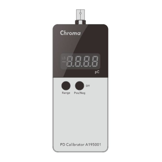
Operation Operation 2.1 Panel Function (1) Output terminal: Generates coulomb value based on the set value. (2) Display area: Displays the current setting and output status (3) Pos/Neg switch/power off button: Switches the PD output polarity or power off the calibrator. -
Page 20: Operation And Display Description
PD Calibrator A195001 User’s Manual 2.2 Operation and Display Description (1) Range switch/power on button Power on: In power off state, long press Range button for 3 seconds and the screen will display the value that is in output state. - Page 21 Operation ► 2000pC range: (2) Pos/Neg switch/power off button Switch output polarity: In power on state, press Pos/Neg (OFF) button to select the output polarity. ► ”+” shows when output polarity is positive ► ”-” shows when output polarity is negative Power off: In power on state, press and hold Pos/Neg (OFF) button 3 seconds, the ...
- Page 22 PD Calibrator A195001 User’s Manual (4) Auto power off If there is no operation over 15 minutes, the calibrator will automatically power off. If you need to use it again, press Range button to turn it on.
-
Page 23: Calibrating Measurement System
Calibrating Measurement System Calibrating Measurement System 3.1 Introduction and Precautions The objective of calibration is to verify that the measurement system can correctly measure the size of specified PD. The calibration of the measurement system must be performed in a complete test circuit. - Page 24 PD Calibrator A195001 User’s Manual As to the equivalent capacitance Ca of DUT, the CO should be much smaller than Ca (CO <0.1 * Ca), otherwise the calibration factor must be considered. However, Ck >> Ca (Ck usually>1nF) in common situation, so CO and Ca will not affect the measurement result.
-
Page 25: Dimensions
Dimensions Dimensions... -
Page 27: Calibration And Maintenance
5.2 Precautions for Maintenance This calibrator has no maintenance operation items for general users. When abnormality occurs to this calibrator, please contact Chroma or its local distributor. Do not conduct maintenance at your own to avoid unnecessary hazard or causing more damage to the device. - Page 28 CHROMA ATE INC. info@chromaate.com www.chromaate.com Copyright by CHROMA ATE INC. All Rights Reserved. All other trade names referenced are the properties of their respective companies.
Need help?
Do you have a question about the A195001 and is the answer not in the manual?
Questions and answers