Table of Contents
Advertisement
Quick Links
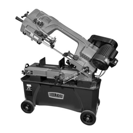
Operating Instructions and Parts Manual
Horizontal-Vertical Band Saw
Model BHVBS-712B
REPRODUCTION OF THIS MANUAL IN ANY FORM WITHOUT WRITTEN APPROVAL OF BAILEIGH
INDUSTRIAL IS PROHIBITED. Baileigh Industrial, Inc. does not assume and hereby disclaims any liability for
any damage or loss caused by an omission or error in this Operator's Manual, resulting from accident,
negligence, or other occurrence.
Baileigh Industrial
P.O. Box
531,1625 Dufek Drive
Manitowoc, WI 54221-0531
Phone: 920.684.4990
Fax: 920.684.3944
Baileigh-Sales@jpwindustries.com
Edition 1 05/2023
Advertisement
Table of Contents

Related Manuals for Baileigh Industrial BHVBS-712B


Summary of Contents for Baileigh Industrial BHVBS-712B
- Page 1 REPRODUCTION OF THIS MANUAL IN ANY FORM WITHOUT WRITTEN APPROVAL OF BAILEIGH INDUSTRIAL IS PROHIBITED. Baileigh Industrial, Inc. does not assume and hereby disclaims any liability for any damage or loss caused by an omission or error in this Operator’s Manual, resulting from accident, negligence, or other occurrence.
-
Page 2: Important Safety Instructions
10. Make all machine adjustments or maintenance with the machine unplugged from the power source. 11. Remove adjusting keys and wrenches. Form a 1.0 IMPORTANT SAFETY habit of checking to see that keys and adjusting wrenches are removed from the machine INSTRUCTIONS before turning it on. -
Page 3: On-Off Switch Padlock
25. Never leave the machine running unattended. WARNING: This product can expose you to Turn the power off and do not leave the chemicals including titanium dioxide which is machine until it comes to a complete stop. known to the State of California to cause cancer, 26. -
Page 4: Table Of Contents
11.1 Mechanical and Electrical Problems ..................... 19 11.2 Operational Problems ........................... 20 12.0 Replacement Parts ............................. 21 12.1.1 BHVBS-712B – Bed and Stand Assembly – Exploded View ............. 21 12.1.2 BHVBS-712B – Bow Assembly – Exploded View ................22 12.1.3 BHVBS-712B – Parts List ........................23 13.0 Electrical Connections –... -
Page 5: About This Manual
4.0 About this Manual This manual is provided by Baileigh Industrial, covering the safe operation and maintenance procedures for the BHVBS-712B Band Saw. This manual contains instructions on installation, safety precautions, general operating procedures, maintenance instructions and parts breakdown. Your machine has been designed and constructed to provide consistent, long-term operation if used in accordance with the instructions as set forth in this document. -
Page 6: Specifications
5.0 Specifications Model Number ..........................BHVBS-712B Stock Number ............................BA1-375 Motor and Electricals: Main Motor: Motor type…………..……………………..………………..totally enclosed fan-cooled, induction, capacitor start Horsepower ..........................3/4 HP (0.56 kW) Phase ................................1 Voltage ........................115/230V (prewired 115V) Cycle .................... - Page 7 Shipping weight ........................418 lbs. (190 kg) The specifications in this manual were current at time of publication, but because of our policy of continuous improvement, Baileigh Industrial reserves the right to change specifications at any time and without prior notice, without incurring obligations.
-
Page 8: Setup And Assembly
6.2 Tools Required for Assembly 6.0 Setup and Assembly • Wrenches, 10mm and 19mm • #2 cross point screwdriver Read understand • Pliers instructions before attempting assembly. Band Saw must be disconnected from power during 6.3 Unpacking and Cleanup all assembly procedures. Failure to comply may 1. - Page 9 4. Install handle with flat washers and nut (C, d) Tighten the 5/16" hex screw and nut (A, Figure 6-5), using 19mm wrench. To install, Figure 6-8). raise bow to vertical position and open guard. CAUTION: Spring-tensioned stop bracket (see Figure 7-1) must be rotated out of the way before raising bow.
-
Page 10: Coolant Tank Preparation
7.0 Electrical Connections This band saw is rated at 115/230V power and is pre-wired for 115 volts. The machine has a plug to be used on a circuit with a grounded outlet that looks like the one pictured in A, Figure 7-1. The motor cable is designed as a male/female plug, as a convenience for users when installing the motor (Figure 7-4). -
Page 11: Voltage Conversion
Figure 7-3: coolant pump wiring Figure 7-1: Grounding 7.3 Extension Cords The use of extension cords is discouraged; try to When operated at 230-volt, this tool is intended for position machines near the power source. If an use on a circuit that has an outlet that looks like the extension cord is necessary, make sure it is in good one illustrated in D, Figure 7-1. -
Page 12: Blade Speed
Figure 8-3: Blade Speed Adjustment Figure 8-1: Disengaging Stop Bracket 6) Tension belt by backing off screws (M) with 3) Remove deflector plate (D). 12mm wrench. Slide motor back into position. 4) Install table plate (B) and secure with two Finger pressure on belt between the pulleys screws. -
Page 13: Blade Replacement
8.5 Blade Replacement 14) Follow blade break-in procedures (sect. 9.1). A general-use variable-tooth blade is provided with 8.6 Blade Guide Bearings this band saw. 1) Disconnect the machine from the power source. Choice of blade pitch is governed by thickness of workpiece: the thinner the workpiece, the more 2) Loosen the bolt (Q, Figure 8-9) and adjust the teeth advised. -
Page 14: Blade Tracking
8.9 Blade Tracking Blade tracking adjustment requires running saw with rear guard open. This adjustment must be completed by qualified persons only. Failure to comply may cause serious injury. Blade tracking has been set by the manufacturer and should not need immediate adjustment. If blade tracking should ever require adjustment: 1) Confirm that blade tension is properly set. -
Page 15: Setting Feed Rate
piece rather than a smaller one. The maximum 4) If adjustment is needed, loosen one nut and thickness variation on any test piece should be no tighten the other (Figure 8-11) on the eye bolt, more than 0.003 inch, per side, per inch of stock until scale indicates 5 to 6 kg (11-13 lb). -
Page 16: Auto Shut-Off Adjustment
8.14 Auto Shut-Off Adjustment The saw is properly adjusted when blade shuts off just after cut completion. To set this: • If saw completes cut but blade continues moving, adjust trip tab (V, Figure 8-13) downward. • If blade stops before cut is complete, adjust trip tab (V) upward. -
Page 17: Evaluating Cutting Efficiency
1) Give machine an overall inspection. Verify that If chips formed are curled, but colored — that is, all guards, covers, etc. are in place and in either blue or straw-colored from heat generated working order, the blade is tensioned properly, during the cut —... -
Page 18: Coolant Level
4) Hold a container under lower right corner of cause crooked cuts, a low cutting rate and/or gear box with one hand while slowly raising bow permanent blade damage. To fill tank, pour coolant with the other. Drain completely. into hole through strainer cup to about 80% of full capacity. -
Page 19: Troubleshooting
11.0 Troubleshooting 11.1 Mechanical and Electrical Problems Symptom Possible Cause Correction * Motor will not start. No incoming power. Check plug connection. If satisfactory, check breaker or fuse. Low voltage. Check power line for proper voltage. Open circuit in motor or loose Inspect all lead connections on motor for connection. -
Page 20: Operational Problems
11.2 Operational Problems Symptom Possible Cause Correction Cuts not square. Blade not square to vise/material. Adjust vise square to blade. Blade surface not perpendicular to Adjust blade guides until perpendicular. table. Workpiece shifting in vise. Properly secure workpiece by tightening vise handles. -
Page 21: Replacement Parts
Non-proprietary parts, such as fasteners, can be found at local hardware stores or may be ordered from Baileigh Industrial. Some parts are shown for reference only and may not be available individually. 12.1.1 BHVBS-712B – Bed and Stand Assembly – Exploded View... -
Page 22: Bhvbs-712B - Bow Assembly - Exploded View
12.1.2 BHVBS-712B – Bow Assembly – Exploded View... -
Page 23: Bhvbs-712B - Parts List
Part No Description Size ....BHVBS-712B-SA ..Stand Assembly (includes #1 thru 5) ............. 1 6 ....HVBS712-06 ....Shipping Brace ....................2 7 ....TS-0051011 ....Hex Cap Screw ............5/16” x 1/2" ....2 9 ....6293226 ..... Phillips Pan Head Machine Screw ......3/16” x 3/8" ....2 10 .... - Page 24 Index No Part No Description Size 64-4 ... HVBS7MW-154 ..Spring Cap ....................1 64-5 ... HVBS7MW-155 ..Socket Head Cap Screw ......... 3/16” x 1/2” ....1 64-6 ... TS-0720091 ....Lock Washer ............3/8" ....... 1 64-7 ... TS-0561031 ....Hex Nut ..............3/8" ....... 1 65 ....
- Page 25 Index No Part No Description Size 125 .... HVBS7MW-81 .... Worm Bushing ....................1 126 .... TS-0206021 ....Socket Head Cap Screw ......... 3/16” x 3/8” ....3 127 .... 414303 ....... Bi-Metal Blade ............3/4x0.035x93 5/8VT ..1 128 ....
- Page 26 ....BHVBS-712B-BDS ..Blade Direction Sticker (not shown) ......63*25mm ...... 1 ....BHVBS-712B-CS ..Coolant Sticker (not shown) ........63*28mm ...... 1 ....BHVBS-712B-TFPS ... Transport Fixed Plate Sticker (not shown) ..... 127*45mm ....1 ....BHVBS-712B-HFCS .. Hydraulic Feed Control Sticker (not shown) .... 57*203mm ....1...
-
Page 27: Electrical Connections - Bhvbs-712B
13.0 Electrical Connections – BHVBS-712B... -
Page 28: Warranty And Service
13.0 Warranty and Service Thank you for purchasing this machine from Baileigh Industrial. We hope that you find it productive and useful to you for a long time to come. Inspection & Acceptance. Buyer shall inspect all Goods within ten (10) days after receipt thereof. Buyer’s payment shall constitute final acceptance of the Goods and shall act as a waiver of the Buyer’s rights to inspect or reject the goods unless otherwise agreed. - Page 29 NOTES...
- Page 30 NOTES...
- Page 31 NOTES...
- Page 32 BAILEIGH INDUSTRIAL 1625 D , WI 54220 UFEK RIVE ANITOWOC : 920.684.4990 F : 920.684.3944 HONE www.baileigh.com...
Need help?
Do you have a question about the BHVBS-712B and is the answer not in the manual?
Questions and answers