Table of Contents
Advertisement
Quick Links
Operating Instructions and Parts Manual
Sliding Dual-Bevel Compound Miter Saw
REPRODUCTION OF THIS MANUAL IN ANY FORM WITHOUT WRITTEN APPROVAL OF
BAILEIGH INDUSTRIAL IS PROHIBITED. Baileigh Industrial does not assume and hereby
disclaims any liability for any damage or loss caused by an omission or error in this Operator's
Manual, resulting from accident, negligence, or other occurrence.
Industrial does not assume and hereby disclaims any liability for any damage or loss caused
by an omission or error in this Operator's Manual, resulting from accident, negligence, or other
occurrence.
Models: BMS-10 and BMS-12
Baileigh Industrial
Manitowoc, WI 54221-0531
Phone: 920.684.4990
Fax: 920.684.3944
Baileigh-Sales@jpwindustries.com
© 2022 Baileigh Industrial
© 2022 Baileigh Industrial
P.O. Box 531
1
Edition 2 07/2022
Edition 1 04/2022
Advertisement
Table of Contents

Related Manuals for Baileigh Industrial BMS-10


Summary of Contents for Baileigh Industrial BMS-10
- Page 1 Baileigh-Sales@jpwindustries.com REPRODUCTION OF THIS MANUAL IN ANY FORM WITHOUT WRITTEN APPROVAL OF BAILEIGH INDUSTRIAL IS PROHIBITED. Baileigh Industrial does not assume and hereby disclaims any liability for any damage or loss caused by an omission or error in this Operator’s Manual, resulting from accident, negligence, or other occurrence.
-
Page 2: Table Of Contents
1.0 Table of Contents 1.0 Table of Contents ....................... 2 THANK YOU & WARRANTY ................... 4 GENERAL NOTES ......................6 2.0 Important Safety Instructions ..................7 2.1 General machine safety warnings ................7 2.2 Miter saw safety warnings ..................8 3.0 About this manual .................... - Page 3 12.0 Troubleshooting BMS-10, BMS-12 Miter Saws ............ 28 13.0 Replacement Parts ....................30 13.1 BMS-10 – Miter Saw Assembly – Exploded View I .......... 31 13.2 BMS-10 – Miter Saw Assembly – Exploded View II ......... 32 13.3 BMS-10 – Miter Saw Assembly – Parts List ............. 33 13.4 BMS-12 –...
-
Page 4: Thank You & Warranty
THANK YOU & WARRANTY Thank you for your purchase of a machine from Baileigh Industrial. We hope that you find it productive and useful to you for a long time to come. Inspection & Acceptance. Buyer shall inspect all Goods within ten (10) days after receipt thereof. Buyer’s payment shall constitute final acceptance of the Goods and shall act as a waiver of the Buyer’s rights to inspect or reject the... - Page 5 • You must obtain a Baileigh Industrial issued RGA number PRIOR to returning any materials. • Returned materials must be received at Baileigh Industrial in new condition and in original packaging. • Altered items are not eligible for return.
-
Page 6: General Notes
Also contact Baileigh Industrial and inform them of the unexpected occurrence. Temporarily suspend installation. Take necessary precautions while loading / unloading or moving the machine to avoid any injuries. -
Page 7: Important Safety Instructions
f) If operating a power tool in a damp location is unavoidable, use a ground fault circuit interrupter (GFCI) protected supply. Use of a DFCI reduces the risk of electric shock. 2.0 Important Safety 3) Personal safety a) Stay alert, watch what you are doing and use common Instructions sense when operating a power tool. -
Page 8: Miter Saw Safety Warnings
these instructions to operate the power tool. Power tools the saw blade to climb on top of the workpiece and violently are dangerous in the hands of untrained users. throw the blade assembly towards the operator. e) Maintain power tools and accessories. Check for misalignment or binding of moving parts, breakage of e) Never cross your hand over the intended line of cutting parts and any other condition that may affect the power... - Page 9 n) The cut-off piece must not be jammed or pressed by any NOTE: The above warning applies only for miter saws with means against the spinning saw blade. If confined, i.e. a brake system. using length stops, the cut-off piece could get wedged WARNING: Drilling, sawing, sanding, or against the blade and thrown violently.
-
Page 10: About This Manual
3.0 About this manual This manual is provided by Baileigh Industrial, covering the safe operation and maintenance procedures for a Baileigh Industrial model BMS-10 and BMS-12 Miter Saw. This manual contains instructions on installation, safety precautions, general operating procedures, maintenance instructions and parts breakdown. Your machine has been designed and constructed to provide consistent, long-term operation if used in accordance with the instructions set forth in this document. -
Page 11: Features And Terminology
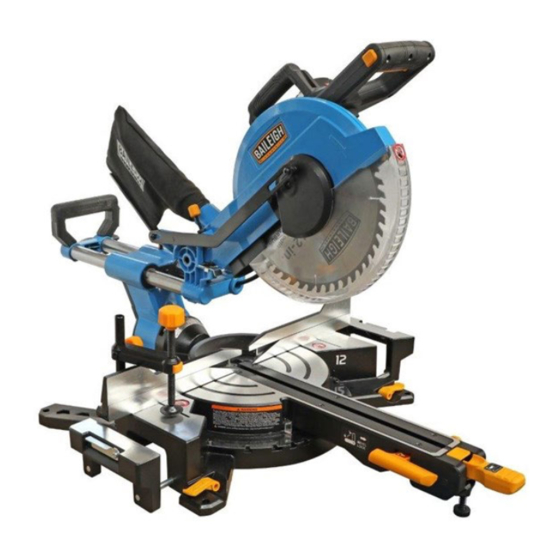
4.0 Features and terminology Figure 4-1: Features and Terminology... -
Page 12: Technical Specifications
5.0 Technical Specifications Table 1 Model Number BMS-10 BMS-12 Power 115VAC, 1PH, 60Hz, 15A Motor 115VAC, 1PH, 60Hz 15A, 1.7kW Blade Speed (n 4000 ±10% rpm Laser Class II, 3V, 400~700 nm Work Light Motor arbor size Ø 5/8 in. (15.875 mm) Ø... -
Page 13: Cutting Capacities
N/A = not applicable The specifications in this manual were current at time of publication, but because of our policy of continuous improvement, Baileigh Industrial reserves the right to change specifications at any time and without prior notice, without incurring obligations. -
Page 14: Setup And Assembly
6.0 Setup and assembly 6.5 Mounting saw to bench For stationary use: Read and understand the entire contents of this manual before attempting Select a location for the saw, such as the top of a assembly or operation. Failure to comply may workbench, that provides sufficient room for handling cause serious injury. -
Page 15: Dust Extraction
6.11 Installing hold-down 1. Insert hold-down post (F, Figure 6-2) into mounting hole located behind left or right fence. 2. Loosen knob (G) to raise or lower clamp support, then tighten knob. 3. Press button (H) to allow clamp to drop onto workpiece, then use knob (J) to tighten clamp against workpiece. - Page 16 8. Remove arbor bolt, outer flange, and blade. (On model BMS-12, also remove reducer sleeve). Do not remove inner flange. Note: Pay attention to the pieces removed, noting their position and direction they face. Wipe pieces clean of any sawdust before installing a new blade.
-
Page 17: Electrical Connections
it still does not fit, contact a qualified electrician to Never use saw without cover plate install the proper outlet. Do not alter the plug in any securely in place and screw tightened down. way. Failure to comply may cause serious injury. If arbor bolt should accidentally loosen, the cover plate Double insulation does not take the place of normal prevents it from falling out, and helps prevent the... -
Page 18: Support Foot
8.1 Support foot 8.2.1 Miter positive stop selection The miter saw table has preset stops for quick and The foot (A, Figure 8-1) can be turned in or out to accurate positioning at common angle settings of 0°, adjust its height. It is designed to provided support for 15°, 22.5°, 31.6°, and 45°... -
Page 19: Fence Adjustment
8.4 Fence adjustment The fence extensions must be extended to left or right, or removed entirely, when making bevel cuts, to prevent blade or guard obstruction. Failure to comply may cause serious injury. Failure to extend the fence will not allow enough space for the blade to pass through. -
Page 20: 45° Bevel Stop Adjustment
NOTE: If lock handle (A) is disengaged and bevel pin (B) has been pulled out, but cutting head still refuses to tilt, the lock nut may have been overtightened for shipping purposes. Remove three screws and open rear cover (see Figure 8-5). Slightly loosen lock nut (N, Figure 8-5) with wrench. -
Page 21: Operation
4. Hold cutting head in this position and turn stop product will increase eye hazard. Refer to Figure screw (H) until it touches plate (G). 9-1. 5. Rotate knurled nut (J) against casting to secure setting. 6. Recheck blade depth by moving cutting head front to back through the full motion of a typical cut along the control arm. -
Page 22: Finishing The Cut
operating handle, and press trigger (see Figure 4- • Return carriage to full rear position after each 1) to start saw. Blade must NOT be contacting crosscut operation. workpiece when trigger is pressed. To crosscut boards that are wider than the length of 6. -
Page 23: Cutting Bowed Material
The charts in sect. 11.0 show miter and bevel settings 9.9 Crown molding for specific angles of compound cuts. Your compound miter saw is suited for the difficult task 9.6 Cutting bowed material of cutting crown molding. To fit properly, crown molding must be compound-mitered with extreme accuracy. -
Page 24: Lower Blade Guard
• 10.4 Commutator brush inspection Periodically, saw dust will accumulate under saw table and base. This could cause difficulty in the movement of the table when setting up a miter cut. To maintain motor efficiency, inspect the two carbon Frequently blow out or vacuum up the saw dust. brushes every two months, or more frequently if saw Turn saw over and blow out dust from beneath is heavily used. -
Page 25: Additional Servicing
Figure 10-1 10.5 Additional servicing Any additional servicing should be performed by authorized service personnel. -
Page 26: Crown Molding Charts
11.0 Crown molding charts 11.1 Crown molding: 90° wall angles Crown molding compound cut with 90° walls. Type of Cut Key Bevel Setting Miter Setting Procedure 1. Position top of molding against fence. Inside corner – Left Side 33.9° 31.6° Right 2. - Page 27 11.2 Crown molding: various wall angles Compound miter and bevel angle settings for wall-to-crown molding angles. 52/38º Crown Molding 45/45º Crown Molding 52/38º Crown Molding 45/45º Crown Molding Angle Angle 0Miter 0Bevel 0Miter 0Bevel 0Miter 0Bevel 0Miter 0Bevel Between Between 0Setting 0Setting 0Setting...
- Page 28 52/38º Crown Molding 45/45º Crown Molding 52/38º Crown Molding 45/45º Crown Molding Angle Angle Miter Bevel Miter Bevel Miter Bevel Miter Bevel Between Between Setting Setting Setting Setting Setting Setting Setting Setting Walls Walls 2.77 3.54 3.19 3.10 1.23 1.58 1.41 1.41 2.47...
-
Page 29: Troubleshooting Bms-10, Bms-12 Miter Saws
12.0 Troubleshooting BMS-10, BMS-12 Miter Saws Symptom Possible Cause Correction * Motor will not start. No incoming power. Check plug connection to receptacle. If satisfactory, check electrical panel for blown fuse or tripped breaker – replace fuse or reset breaker. -
Page 30: Replacement Parts
13.0 Replacement Parts Replacement parts are listed on the following pages. To order parts or reach our service department, call 1-800-274- 6848 Monday through Friday, 8:00 a.m. to 5:00 p.m. CST. Having the Model Number and Serial Number of your machine available when you call will allow us to serve you quickly and accurately. -
Page 31: Bms-10 - Miter Saw Assembly - Exploded View I
13.1 BMS-10 – Miter Saw Assembly – Exploded View I... -
Page 32: Bms-10 - Miter Saw Assembly - Exploded View Ii
13.2 BMS-10 – Miter Saw Assembly – Exploded View II... -
Page 33: Bms-10 - Miter Saw Assembly - Parts List
13.3 BMS-10 – Miter Saw Assembly – Parts List Index No Part No Description Size 001 ... JMS10X-001 .... Miter Angle Scale ..................1 002 ... TS-2245122 ..... Socket Head Button Screw ........M5x12 ......3 003 ... TS-2284082 ..... Pan Head Machine Screw ........M4x8 ......4 004 ... - Page 34 Index No Part No Description Size 049 ... TS-1522021 ..... Socket Set Screw ..........M5x8 ......3 050 ... JMS10X-050 .... Stop Plate ....................1 051 ... JMS10X-051 .... Spring ...................... 1 052 ... JMS10X-052 .... Lock Axis ....................1 053 ...
- Page 35 Index No Part No Description Size 101 ... TS-1550031 ..... Flat Washer ............5 mm ......8 102 ... JMS10X-102 .... Bearing Plate ................... 2 103 ... JMS10X-103 .... Felt ......................4 104 ... JMS10X-104 .... Bearing ..............LM254035 ....4 105 ...
- Page 36 Index No Part No Description Size 153 ... F001231 ....Pan Head Machine Screw ........M5-0.8x70 ....2 154 ... JMS10X-154 .... Stator ....................... 1 155 ... BB-6001ZZ ....Ball Bearing ............6001-2RS ....1 156 ... JMS10X-156 .... Damping Ring ..................1 157 ...
- Page 37 208 ... BMS10-208 ....Pin ......................1 209 ... TS-1512011 ..... Socket Head Flat Screw ........M4x10 ......3 210 ... LM000391 ....ID Label, BMS-10 ..................1 211 ... JDR34-026 ....Self-Tapping Screw ..........ST4.2x9.5 mm .... 1 212 ...
-
Page 38: Bms-12 - Miter Saw Assembly - Exploded View I
13.4 BMS-12 – Miter Saw Assembly – Exploded View I... -
Page 39: Bms-12 - Miter Saw Assembly - Exploded View Ii
13.5 BMS-12 – Miter Saw Assembly – Exploded View II... -
Page 40: Bms-12 - Miter Saw Assembly - Parts List
13.6 BMS-12 – Miter Saw Assembly – Parts List Index No Part No Description Size 001 ... JMS12X-001 .... Miter Angle Scale ..................1 002 ... TS-2246122 ..... Socket Head Button Screw ........M6x12 ......3 003 ... TS-2284082 ..... Pan Head Machine Screw ........M4x8 ......4 004 ... - Page 41 Index No Part No Description Size 049 ... JMS10X-041 .... Adjustable Foot ..................1 050 ... JMS10X-042 .... Spring ...................... 1 051 ... JMS10X-044 .... Support ....................1 052 ... TS-1522021 ..... Socket Set Screw ..........M5x8 ......3 053 ...
- Page 42 Index No Part No Description Size 100 ... TS-1513011 ..... Socket Head Flat Screw ........M5x10………..… ..4 101 ... JMS12X-101 .... Protective Sleeve ..................1 102 ... JMS12X-102 .... Slide Bar, Right ..................1 103 ... JMS12X-103 .... Slide Bar, Left ..................1 104 ...
- Page 43 Index No Part No Description Size 151 ... JMS10X-147 .... Seal ......................1 152 ... JMS10X-148 .... Lens ......................1 153 ... JMS10X-149 .... Deflector ....................1 154 ... JMS10X-150 .... Motor Plate ....................1 155 ... TS-2361051 ..... Lock Washer ............5 mm ......5 156 ...
- Page 44 Index No Part No Description Size 202 ... JMS12X-202 .... Reducer ..............5/8” x1”x 0.11” .... 1 203 ... JMS10X-196 .... Outer Flange ................... 1 204 ... JMS10X-198 .... Screw (LH Threads) ..........M8x20 Left ....1 205 ... JMS12X-205 .... Spring ...................... 1 206 ...
-
Page 45: Electrical Connections - Bms-10, Bms-12
14.0 Electrical Connections – BMS-10, BMS-12... - Page 46 Notes...
- Page 47 Notes...
- Page 48 BAILEIGH INDUSTRIAL 1625 D , WI 54220 UFEK RIVE ANITOWOC : 920.684.4990 F : 920.684.3944 HONE www.baileigh.com...
Need help?
Do you have a question about the BMS-10 and is the answer not in the manual?
Questions and answers