Table of Contents
Advertisement
Quick Links
OPERATOR'S MANUAL
TABLE SAW
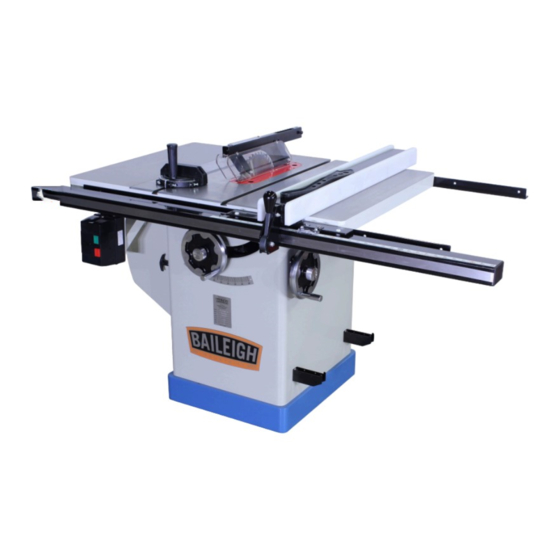
MODEL: TS-1040E-30 & 50-V3
Baileigh Industrial Holdings LLC
P.O. Box 531
Manitowoc, WI 54221-0531
Phone: 920.684.4990
Fax: 920.684.3944
Baileigh-Sales@jpwindustries.com
REPRODUCTION OF THIS MANUAL IN ANY FORM WITHOUT WRITTEN APPROVAL OF BAILEIGH INDUSTRIAL
HOLDINGS LLC IS PROHIBITED. Baileigh Industrial Holdings LLC, Inc. does not assume and hereby disclaims any
liability for any damage or loss caused by an omission or error in this Operator's Manual, resulting from accident,
negligence, or other occurrence.
Rev. 07/2021
© 2021 Baileigh Industrial Holdings LLC
Advertisement
Table of Contents

Related Manuals for Baileigh Industrial TS-1040E-30


Summary of Contents for Baileigh Industrial TS-1040E-30
- Page 1 REPRODUCTION OF THIS MANUAL IN ANY FORM WITHOUT WRITTEN APPROVAL OF BAILEIGH INDUSTRIAL HOLDINGS LLC IS PROHIBITED. Baileigh Industrial Holdings LLC, Inc. does not assume and hereby disclaims any liability for any damage or loss caused by an omission or error in this Operator’s Manual, resulting from accident, negligence, or other occurrence.
-
Page 2: Table Of Contents
Table of Contents THANK YOU & WARRANTY ..................1 INTRODUCTION ......................3 GENERAL NOTES ......................3 SAFETY INSTRUCTIONS ....................4 SAFETY PRECAUTIONS ....................7 Dear Valued Customer: ....................7 TECHNICAL SUPPORT ....................10 TECHNICAL SPECIFICATIONS ................... 11 INTENDED USE ......................12 Tools: ......................... - Page 3 Lubrication ......................... 41 Changing the Belt ...................... 41 TROUBLESHOOTING ....................42 ELECTRICAL DIAGRAM ....................43 TABLE & CABINET PARTS DIAGRAM - A ..............44 Table & Cabinet Parts List – A................... 45 TRUNNION & MOTOR PARTS DIAGRAM - B ............. 47 Trunnion &...
-
Page 4: Thank You & Warranty
THANK YOU & WARRANTY Thank you for your purchase of a machine from Baileigh Industrial Holdings LLC. We hope that you find it productive and useful to you for a long time to come. Inspection & Acceptance. Buyer shall inspect all Goods within ten (10) days after receipt thereof. Buyer’s payment shall constitute final acceptance of the Goods and shall act as a waiver of the Buyer’s rights to inspect or... - Page 5 We apologize for any discrepancies that may occur. Baileigh Industrial Holdings LLC reserves the right to make any and all changes deemed necessary in the course of business including but not limited to pricing, product specifications, quantities, and product availability.
-
Page 6: Introduction
INTRODUCTION The quality and reliability of the components assembled on a Baileigh Industrial Holdings LLC machine guarantee near perfect functioning, free from problems, even under the most demanding working conditions. However, if a situation arises, refer to the manual first. If a solution cannot be found, contact the distributor where you purchased our product. -
Page 7: Safety Instructions
IMPORTANT PLEASE READ THIS OPERATORS MANUAL CAREFULLY It contains important safety information, instructions, and necessary operating procedures. The continual observance of these procedures will help increase your production and extend the life of the equipment. SAFETY INSTRUCTIONS LEARN TO RECOGNIZE SAFETY INFORMATION This is the safety alert symbol. - Page 8 SAVE THESE INSTRUCTIONS. Refer to them often and use them to instruct others. PROTECT EYES Wear safety glasses or suitable eye protection when working on or around machinery. PROTECT AGAINST NOISE Prolonged exposure to loud noise can cause impairment or loss of hearing.
- Page 9 HIGH VOLTAGE USE CAUTION IN HIGH VOLTAGE AREAS. DO NOT assume the power to be off. FOLLOW PROPER LOCKOUT PROCEDURES. EMERGENCY STOP BUTTON In the event of incorrect operation or dangerous conditions, the machine can be stopped immediately by pressing the E-STOP button.
-
Page 10: Safety Precautions
SAFETY PRECAUTIONS Wood working can be dangerous if safe and proper operating procedures are not followed. As with all machinery, there are certain hazards involved with the operation of the product. Using the machine with respect and caution will considerably lessen the possibility of personal injury. However, if normal safety precautions are overlooked or ignored, personal injury to the operator may result. - Page 11 6. Blade Height. Adjust the blade to the correct height above the piece part so it does not kickback toward the operator causing injury. 7. Remove any adjusting tools. Before operating the machine, make sure any adjusting tools have been removed. 8.
- Page 12 24. Know the location of the ON - OFF switch and the “E”- STOP button. 25. Removing Piece Parts. Before removing cut-offs, always turn the saw OFF, and wait for the blade to stop turning, to avoid contact with a moving blade. 26.
-
Page 13: Technical Support
40. A push block and/or a push stick must be used if the workpieces is less than 5” (127mm) to prevent your hands from getting too close to the saw blade. Push block must be used to cut narrow workpieces and, when necessary, to push the workpiece against the fence, a push block can be easily made by the operator. -
Page 14: Technical Specifications
TECHNICAL SPECIFICATIONS Weight 477lbs (216kg) 60" x 38" x 40" Dimensions W x D x H (1524 x 965 x 1016mm) Foot Print (L x W) 20.25" x 19.625" (514 x 499mm) Magnetic with Thermal Overload Switch Protection Electrical Switch Voltage 220V / 1ph / 60hz Type TEFC Capacitor Start Induction... -
Page 15: Intended Use
50” Front of Table to Center of Blade 14.5" (368mm) Front of Table to Blade, Maximum Cut 10" (255mm) 34.25" x 2.9375" x .59" Fence Information Fence Size (L x W x H) (870 x 75 x 15mm) Miter Gauge Slot Type T-Slot Miter Gauge Information... -
Page 16: Unpacking And Checking Contents
UNPACKING AND CHECKING CONTENTS Your Baileigh machine is shipped complete. Separate all parts from the packing material and check each item carefully. Make certain all items are accounted for before discarding any packing material. WARNING: SUFFOCATION HAZARD! Immediately discard any plastic bags and packing materials to eliminate choking and suffocation hazards to children and animals. -
Page 17: Contents Of The Shipping Container
Contents of the Shipping Container Main Saw Container Table Saw Switch Table Insert Extension Tables Side Motor Cover The small box consists of the following items: Blade Guard Assembly (E) Riving Knife and Pawl Assembly (F) Handwheel and Swivel Handle (G) Lock Knob (H) Large Hooks (J) Small Hook (K) -
Page 18: Transporting And Lifting
TRANSPORTING AND LIFTING NOTICE: Lifting and carrying operations should be carried out by skilled workers, such as a truck operator, crane operator, etc. If a crane is used to lift the machine, attach the lifting chain carefully, making sure the machine is well balanced. Follow these guidelines when lifting with truck or trolley: •... - Page 19 • Remove scrap and waste materials regularly, and make sure the work area is free from obstructing objects. • It is important to maintain free area around the machine, which is required for the working place. If any long material is machined, it is necessary to have a sufficient room in front of the machine as well behind it in the places of material input and output.
-
Page 20: Getting To Know Your Machine
GETTING TO KNOW YOUR MACHINE Identification On/Off Switch; Power Box Front Rail Tube / Fence Tube Left Extension Wing Fence Lock Handle Miter Gauge Blade Tilt Handwheel w/Center Lock Blade Guard 4” (100mm) Dust Port; (On back) Fence Fence Storage Supports Right Extension Wing Table Tilt Scale Back Rail... -
Page 21: Assembly And Set Up
ASSEMBLY AND SET UP WARNING: For your own safety, DO NOT connect the machine to the power source until the machine is completely assembled and you read and understand the entire instruction manual. 1. Using the handwheel for the saw blade height on the front of the cabinet, raise the motor to the full up position. - Page 22 Extension Wings 1. Remove the red shipping bracket (A) securing the electrical box to the table. The bracket will not be used again for normal operation. 2. Carefully allow the electrical box to hang by the cords until ready to fasten to the front of the table during the installation of the fence rails.
-
Page 23: Install The Rail & Fence & Extension Table
Install the Rail & Fence & Extension Table 1. Use the drawing below to assist in laying out and assembling the fence rails and the extension tables for the 30” and the 50” table. 2. Install the front rail by working from the left end of the table toward the right and loosely install the mounting screws to support and align the front rail using the 1/4"... - Page 24 3. Using the straight edge and ruler or a combination square as shown, measure from the table top to the top of the rail and allow for a 9/16” (14.28mm) gap between the bottom of the straightedge and the top of the rail.
- Page 25 Wooden Extension Table The wood extension table sits flush against the saw table and along the inside of the fence rails. The extension table is not bolted to the saw table, it is bolted only to the rails. The extension table and saw table must be aligned properly so the fence will slide smoothly from one to the other.
- Page 26 11. Install the three 1/4" flat head screws and hardware into the holes in the front edge of extension table. Finger tighten only. 12. Install the three 1/4" hex cap screws and hardware into the holes in the rear edge of extension table. Finger-tighten only.
-
Page 27: Fence Assembly
FENCE ASSEMBLY Align the Fence Parallel to the Blade WARNING: The rip fence must be parallel to the blade during operation. Failure to set the rip fence parallel to the blade can result in kickback and possible serious injury. 1. Disconnect and lockout power to the saw! 2. -
Page 28: Align The Rip Fence Perpendicular (90°) To The Table
Align the Rip Fence Perpendicular (90°) to the Table 1. Disconnect and lockout power to the saw! 2. Place a square on the table against the fence and look for a gap between the square and the fence (bottom and top) or the table. 3. -
Page 29: Install / Change The Blade
Install / Change the Blade The standard blade included with the saw is a general-purpose starter blade. It is recommended that blades be chosen and sourced from a reputable supplier based upon the specific materials and type of cutting being performed. WARNING: Turn the power switch “OFF”... -
Page 30: Riving Knife And Guard Installation
Riving Knife and Guard Installation CAUTION: After changing a saw blade, always check that the Riving knife or Blade Guard is correctly set! 1. Before installing onto the saw, the anti- kickback pawl (E) must be separated from the riving knife (H). -
Page 31: Riving Knife Adjustment
8. In similar manner attach the guard (C) by pressing and holding the quick-release button (B) and inserting the lock pin of the guard into the appropriate slot (G) on the riving knife. 9. You should feel a snap as each piece locks in position. - Page 32 If adjustment is required: 1. Remove the table insert. 2. Loosen the lock handle (A) and remove the riving knife, making a note as to which direction the riving knife needs to be moved to align it with the saw blade.
-
Page 33: Dust Collection
Dust collection It is recommended that you use a dust collector (not included) when using this machine. The minimum air flow requirements for this machine are listed below. The machine comes with a 4” (100mm) dust port located on the side of the machine. The dust extraction equipment is to be switched on before commencing machining. -
Page 34: Electrical
ELECTRICAL CAUTION: HAVE ELECTRICAL UTILITIES CONNECTED TO MACHINE BY A CERTIFIED ELECTRICIAN! Check if the available power supply is the same as listed on the machine nameplate. WARNING: Make sure the grounding wire (green) is properly connected to avoid electric shock. DO NOT switch the position of the green grounding wire if any electrical plug wires are switched during hookup. -
Page 35: Power Cord Connection
• Improper connection of the equipment-grounding conductor can result in risk of electric shock. The conductor with insulation having an outer surface that is green with or without yellow stripes is the equipment-grounding conductor. If repair or replacement of the electric cord or plug is necessary, do not connect the equipment-grounding conductor to a live terminal. -
Page 36: Adjustment
ADJUSTMENT WARNING: Make sure the electrical disconnect is OFF before working on the machine. Always follow proper safety precautions when working on or around any machinery. Handwheel Adjustments 1. The front handwheel (A) controls the raising and lowering of the blade (blade height). 2. -
Page 37: Miter Gauge
Miter Gauge 1. Operate miter gauge by loosening the lock knob (A) and turning the miter body (B) to the desired angle. To move gauge beyond index stops of 45º and 90º, flip down the stop (C). 2. Adjust index stops by turning one of three adjustment screws (D). -
Page 38: Adjusting 45º And 90º Positive Stops
Adjusting 45º and 90º Positive Stops The stops have been adjusted at the factory. After a period of use, or, after moving the saw to another location, the stops may no longer be set properly. To check and adjust the stops: 1. -
Page 39: Operation
c. Loosen the jam nut and turn adjusting stop screw (B) on the front trunnion in, or out until the blade is at 90º. d. Hold the adjustment bolt in position and tighten the jam nut. 10. With the saw blade still in the 90º position, check that the pointer is pointing accurately at the 0º... -
Page 40: Operation
Operation Plain sawing includes ripping and crosscutting, plus a few other standard operations of a fundamental nature. • As with all power tools there is a certain amount of hazard involved with the operation and use of the saw. • Using the saw with the respect and caution demanded as far as safety precautions are concerned will considerably lessen the possibility of personal injury. -
Page 41: Ripping
Ripping Ripping is the operation of making a lengthwise cut through a board. • The rip fence is used to position and guide the work stock. • One edge of the work stock rides against the rip fence while the flat side of the board rest on the table. -
Page 42: Using Dado Blade Set And Dado Insert
Using Dado Blade Set and Dado Insert WARNING: Blades are dangerously sharp. Use extreme caution when working with or around the blade. Wear proper safety protection such as heavy gloves. Dadoing is cutting a rabbet or a wide groove into the work. -
Page 43: Maintenance
MAINTENANCE WARNING: Make sure the electrical disconnect is OFF before working on the machine. Maintenance should be performed on a regular basis following proper safety precautions. This table saw requires very little maintenance other than minor lubrication and cleaning. The following sections detail what will need to be done to assure continued operation of your saw. -
Page 44: Cleaning
• Check the drive belt for tightness. It should be snug but not overly tight. Readjust or replace belt as required. • Use a mill file to remove any nicks or dings from the infeed or outfeed tables. Note: Proper maintenance can increase the life expectancy of your machine. Cleaning Cleaning the saw is relatively easy. -
Page 45: Troubleshooting
TROUBLESHOOTING WARNING: Disconnect machine from the power source before attempting any troubleshooting Issue Possible Cause Solution Overload tripped. Allow motor to cool and reset by Saw unplugged from wall or pushing off switch. Saw stops or will motor Fuse blown or circuit Check all plug connections. -
Page 46: Electrical Diagram
Dull blade. Replace blade. Letting go of material before it is Push material all the way past blade past blade. before releasing work. Anti-kick back plates dull. Replace or sharpen kick back plates. Blade does not Sawdust and debris in raising Clean and re-grease. - Page 47 TABLE & CABINET PARTS DIAGRAM - A...
- Page 48 Table & Cabinet Parts List – A Item Part No. Description TS1040EV3-A1-11 Miter Gauge Assembly (#1-11) TS1040EV3-A1 Lock Knob TS1040EV3-A2 Miter Gauge Body TS1040EV3-A3 Hex Nut M5 TS1040EV3-A4 Pointer TS1040EV3-A5 Stop Link TS1040EV3-A6 Socket Set Screw M4x4 TS1040EV3-A7 Special Pin M3x6 TS1040EV3-A8 Hex Cap Screw M5x20 TS1040EV3-A9...
- Page 49 Item Part No. Description TS1040EV3-A35 Warning Label TS1040EV3-A36 Baileigh Label TS1040EV3-A38 Cabinet TS1040EV3-A39 Hex Cap Screw M6x50 TS1040EV3-A40 Flat Washer 1/4 TS1040EV3-A41 Spring TS1040EV3-A42 Foam Strip TS1040EV3-A43 Motor Cover TS1040EV3-A44 Nylon Insert Lock Nut M6 TS1040EV3-A45 Handle TS1040EV3-A47 Socket Head Cap Screw 7/16-14x3/4 TS1040EV3-A48 Flat Washer 3/16 TS1040EV3-A49...
-
Page 50: Trunnion & Motor Parts Diagram - B
TRUNNION & MOTOR PARTS DIAGRAM - B... -
Page 51: Trunnion & Motor Parts List - B
Trunnion & Motor Parts List – B Item Part No. Description TS1040EV3-B101 Arbor Nut TS1040EV3-B102 Arbor Flange TS1040EV3-B104 Arbor with Flange TS1040EV3-B105 Key M5x44 TS1040EV3-B106 Ball Bearing 6203ZZ TS1040EV3-B107 Wave Washer TS1040EV3-B108 Rear Bearing Load Spacer 108-1 TS1040EV3-B108-1 Front Bearing Load Spacer TS1040EV3-B109 Socket Set Screw 1/4-20x3/8 TS1040EV3-B110... - Page 52 Item Part No. Description TS1040EV3-B131F Motor Fan (not shown) TS1040EV3-BC-600125 Start Capacitor (not shown) 2HP, 1Ph motor TS1040EV3-BC-040250 Run Capacitor (not shown) 2HP, 1Ph motor TS1040EV3-B132 Socket Head Cap Screw 3/8-16x1-1/2 TS1040EV3-B133 Rear Trunnion Bracket TS1040EV3-B134 Hex Nut 3/8-16 TS1040EV3-B135 Socket Head Cap Screw 3/8-16x1 TS1040EV3-B136 Spring Pin M8x25...
- Page 53 Item Part No. Description TS1040EV3-B161 Shield Plate TS1040EV3-B162 Round Head Screw 1/4-20x3/8 TS1040EV3-B163 Pointer TS1040EV3-B164 Pointer Bracket TS1040EV3-B165 Pan Head Screw #10-24x2 TS1040EV3-B166 Guide Block TS1040EV3-B167 Flat Washer 3/8 TS1040EV3-B169 Tilt Shaft TS1040EV3-B170 Wrench TS1040EV3-B171 Hose 700mm TS1040EV3-B172 Plate TS1040EV3-B173 Socket Head Cap Screw 5/16-18x3/4 TS1040EV3-B174 Chip Plate...
-
Page 54: Blade Guard Parts Diagram - C
Item Part No. Description TS1040EV3-B192 Spring TS1040EV3-B193 Clamping Block TS1040EV3-B194 Flat Head Socket Screw M6X20 TS1040EV3-B195 Locking Handle TS1040EV3-B196 Nylon Insert Lock Nut M8 TS1040EV3-B197 Spring Shim Ring TS1040EV3-B198 C-Ring S52 BLADE GUARD PARTS DIAGRAM - C... -
Page 55: Blade Guard Parts List - C
Blade Guard Parts List - C Item Part No. Description TS1040EV3-C1 Riving Knife TS1040EV3-CBGA Blade Guard Assembly (Index #2 thru 16, 21, 22) TS1040EV3-C2 Bushing TS1040EV3-C3 Blade Guard Body TS1040EV3-C4 Blade Guard Side Shield TS1040EV3-C5 Linking Plate TS1040EV3-C6 Flat Washer M6 TS1040EV3-C7 Flat Head Socket Screw M6 x 16 TS1040EV3-C8... -
Page 56: Fence 30/50 Parts Diagram - D
FENCE 30/50 PARTS DIAGRAM - D... -
Page 57: Fence 30/50 Parts List - D
Fence 30/50 Parts List - D Item Part No. Description TS1040EV3-D1-26 Fence (includes #1-26) TS1040EV3-D1 Left Side Plate TS1040EV3-D2 Fence Body Assembly TS1040EV3-D3 Tube Cover TS1040EV3-D4 Right Side Plate TS1040EV3-D5 Lock Nut 1/4”-20 TS1040EV3-D6 Set Screw 3/8”-16 x 3/8” TS1040EV3-D7 Fluoroway Pad TS1040EV3-D8 TS1040EV3-D9... -
Page 58: Fence Rail 30/50 Parts Diagram - E
FENCE RAIL 30/50 PARTS DIAGRAM - E... -
Page 59: Fence Rail 30/50 Parts List - E
Fence Rail 30/50 Parts List - E Item Part No. Description TS1040EV3-E113-30 30” Rail Set (includes #1-13) TS1040EV3-E113-50 50” Rail Set (includes #1-13) TS1040EV3-E150 Front Rail (50”) TS1040EV3-E130 Front Rail (30”) TS1040EV3-E2 Flat Head Screw 1/4”-20 x 1-1/2” TS1040EV3-E3 Flat Washer 1/4” TS1040EV3-E4 Lock Washer 1/4”... -
Page 60: Fence Leg Parts Diagram - F
Fence Leg Parts List - F Item Part No. Description TS1040EV3-F1 TS1040EV3-F2 Hex Nut 3/8”-16 TS1040EV3-F3 Adjusting foot TS1040EV3-F4 Machine Screw M5×16 BAILEIGH INDUSTRIAL HOLDINGS LLC 1625 D , WI 54220 UFEK RIVE ANITOWOC : 920. 684. 4990 F : 920. 684. 3944 HONE www.baileigh.com...
Need help?
Do you have a question about the TS-1040E-30 and is the answer not in the manual?
Questions and answers