Table of Contents
Advertisement
Quick Links
OPERATOR'S MANUAL
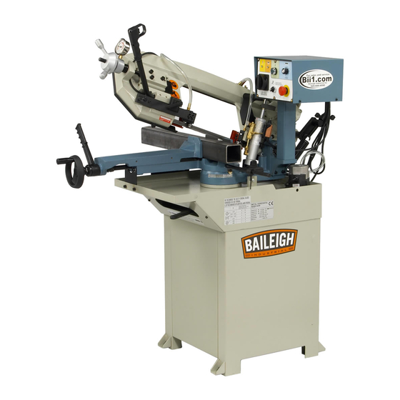
HORIZONTAL BAND SAW
MODEL: BS-210M
Baileigh Industrial, Inc.
P.O. Box 531
Manitowoc, WI 54221-0531
Phone: 920.684.4990
Fax: 920.684.3944
sales@baileighindustrial.com
REPRODUCTION OF THIS MANUAL IN ANY FORM WITHOUT WRITTEN APPROVAL OF BAILEIGH INDUSTRIAL, INC.
IS PROHIBITED. Baileigh Industrial, Inc. does not assume and hereby disclaims any liability for any damage or loss
caused by an omission or error in this Operator's Manual, resulting from accident, negligence, or other occurrence.
Rev. 01/2015
© 2015 Baileigh Industrial, Inc.
Advertisement
Table of Contents

Related Manuals for Baileigh Industrial BS-210M


Summary of Contents for Baileigh Industrial BS-210M
- Page 1 REPRODUCTION OF THIS MANUAL IN ANY FORM WITHOUT WRITTEN APPROVAL OF BAILEIGH INDUSTRIAL, INC. IS PROHIBITED. Baileigh Industrial, Inc. does not assume and hereby disclaims any liability for any damage or loss caused by an omission or error in this Operator’s Manual, resulting from accident, negligence, or other occurrence.
-
Page 2: Table Of Contents
Table of Contents THANK YOU & WARRANTY ..................1 INTRODUCTION ......................3 GENERAL NOTES ......................3 SAFETY INSTRUCTIONS ....................4 SAFETY PRECAUTIONS ....................6 TECHNICAL SPECIFICATIONS ..................8 TECHNICAL SUPPORT ....................8 UNPACKING AND CHECKING CONTENTS ..............9 Cleaning ........................9 TRANSPORTING AND LIFTING .................. - Page 3 LUBRICATION AND MAINTENANCE ................33 Oils for Lubricating Coolant ..................34 Oil Disposal ....................... 34 Coolant System Maintenance ..................34 Gearbox Maintenance ....................35 Storing Machine for Extended Period of Time ............35 ELECTRICAL SCHEMATIC ..................36 FAULT DISPLAYS ......................38 Error Trip Messages of Drive ..................
-
Page 4: Thank You & Warranty
THANK YOU & WARRANTY Thank you for your purchase of a machine from Baileigh Industrial. We hope that you find it productive and useful to you for a long time to come. Inspection & Acceptance. Buyer shall inspect all Goods within ten (10) days after receipt thereof. Buyer’s payment shall constitute final acceptance of the Goods and shall act as a waiver of the Buyer’s rights to inspect or... - Page 5 • A 30% re-stocking fee applies to all returns. Baileigh Industrial makes every effort to ensure that our posted specifications, images, pricing and product availability are as correct and timely as possible. We apologize for any discrepancies that may occur. Baileigh Industrial reserves the right to make any and all changes deemed necessary in the course of business including but not limited to pricing, product specifications, quantities, and product availability.
-
Page 6: Introduction
After receiving your equipment remove the protective container. Do a complete visual inspection, and if damage is noted, photograph it for insurance claims and contact your carrier at once, requesting inspection. Also contact Baileigh Industrial and inform them of the unexpected occurrence. Temporarily suspend installation. -
Page 7: Safety Instructions
IMPORTANT PLEASE READ THIS OPERATORS MANUAL CAREFULLY It contains important safety information, instructions, and necessary operating procedures. The continual observance of these procedures will help increase your production and extend the life of the equipment. SAFETY INSTRUCTIONS LEARN TO RECOGNIZE SAFETY INFORMATION This is the safety alert symbol. - Page 8 SAVE THESE INSTRUCTIONS. Refer to them often and use them to instruct others. PROTECT EYES Wear safety glasses or suitable eye protection when working on or around machinery. PROTECT AGAINST NOISE Prolonged exposure to loud noise can cause impairment or loss of hearing.
-
Page 9: Safety Precautions
SAFETY PRECAUTIONS Metal working can be dangerous if safe and proper operating procedures are not followed. As with all machinery, there are certain hazards involved with the operation of the product. Using the machine with respect and caution will considerably lessen the possibility of personal injury. However, if normal safety precautions are overlooked or ignored, personal injury to the operator may result. - Page 10 11. Do not overreach. Maintain proper footing and balance at all times. DO NOT reach over or across a running machine. 12. Stay alert. Watch what you are doing and use common sense. DO NOT operate any tool or machine when you are tired. 13.
-
Page 11: Technical Specifications
TECHNICAL SPECIFICATIONS 8.26" x 3.75” (210 x 95mm) Capacity Rectangular 90° Capacity Round 90° / 45° / 60° 6.875" (175mm) / 4.875" (124mm) / 2.94" (75mm) 6.875 x 6.875” (175 x 175mm) / 4.375” x 4.375” (110 Capacity Square 90° / 45° / 60° x 110mm) / 2.44”... -
Page 12: Unpacking And Checking Contents
UNPACKING AND CHECKING CONTENTS Your Baileigh machine is shipped complete in one crate. Separate all parts from the packing material and check each item carefully. Make certain all items are accounted for before discarding any packing material. WARNING: SUFFOCATION HAZARD! Immediately discard any plastic bags and packing materials to eliminate choking and suffocation hazards to children and animals. -
Page 13: Transporting And Lifting
TRANSPORTING AND LIFTING Follow these guidelines when lifting: • Use proper lifting techniques when moving the saw from location to location. • Make sure the machine is balanced, level, and securely tied or strapped to the transport vehicle or device so that all the supporting feet are taking the weight of the machine and no rocking is taking place. -
Page 14: Anchoring The Machine
Anchoring the Machine • Once positioned, anchor the machine to the floor, as shown in .31" the diagram, using bolts and expansion plugs or sunken tie rods that connect through holes in the base of the stand. (7.87mm) .50" (12.7mm) OVERALL DIMENSIONS... -
Page 15: Getting To Know Your Machine
GETTING TO KNOW YOUR MACHINE... - Page 16 Item Description Function Vise Hand Wheel Turning hand-wheel opens and closes vise Vise Lever Quickly clamp and unclamp material Vise Holds front and rear jaws for clamping Blade Tension Handwheel To increase or decrease blade tension Blade Tension Gauge Reads tension in Kgs/cm Trigger Switch For starting saw motor in manual mode Blade Guide Assembly, Front...
- Page 17 Item Description Function Main connect switch Controls the power to the machine. Power indicator light Illuminates when the main power is ON. Press to start the saw blade when Mode selector is Auto start cutting button in Auto Mode Emergency push button Press to stop all saw motor function.
- Page 18 Machine Base After assembly, the machine base becomes the structure that supports the saw bow, the vise, the coolant pump, the bar stop, and the swing arm. Quick Clamp Vise Place the piece part between the vise jaws and have it rest next to the fixed vise jaw.
-
Page 19: Assembly And Set Up
ASSEMBLY AND SET UP WARNING: For your own safety, DO NOT connect the machine to the power source until the machine is completely assembled and you read and understand the entire instruction manual. 1. Assemble the stand as shown in the Parts Identification Drawing. -
Page 20: Electrical
ELECTRICAL CAUTION: HAVE ELECTRICAL UTILITIES CONNECTED TO MACHINE BY A CERTIFIED ELECTRICIAN! Check if the available power supply is the same as listed on the machine nameplate. WARNING: Make sure the grounding wire (green) is properly connected to avoid electric shock. DO NOT switch the position of the green grounding wire if any electrical plug wires are switched during hookup. -
Page 21: Power Cord Connection
cord or plug is necessary, do not connect the equipment-grounding conductor to a live terminal. • Check with a qualified electrician or service personnel if the grounding instructions are not completely understood, or if in doubt as to whether the tool is properly grounded. •... -
Page 22: Before Each Use
BEFORE EACH USE • For dusty operations, wear a face shield along with safety goggles. • It is important to choose the right blade for the material and the type of cutting you plan to do. This saw is equipped with a bi-metallic blade which can be used to cut stainless steel, steel, iron, brass, aluminum, wood, plastic. -
Page 23: Blade Care
BLADE CARE The bandsaw blade is subjected to a tremendous amount of strain. Make sure to always use the appropriate feed rate for the type material you are cutting. Be sure to select a blade of the proper width, style, and pitch that will produce the best cut in your material. -
Page 24: Blade Terminology
Blade Terminology The widest part of the blade measured from the back edge of the BLADE WIDTH blade to the tip of the tooth. GULLET DEPTH The distance from the tooth tip to the bottom of the curved area. The angle of the tooth face from a line perpendicular to the length TOOTH RAKE of the blade. -
Page 25: Cutting And Advance Speed
CHOOSING A SAW BLADE Baileigh Industrial offers a wide selection of tooth styles for various cutting applications. Please phone Baileigh Industrial to have one of our technicians assist you in selecting the proper band saw blade for your cutting applications. -
Page 27: Blade Structure
Blade structure Bi-metal blades are the most commonly used. They consist of a silicon-steel blade backing by a laser welded high speed steel (HHS) cutting edge. The type of stocks are classified in M2, M42, M51 and differ from each other because of their major hardness due to the increasing percentage of Cobalt (Cc) and molybdenum (Mo) contained in the metal alloy. -
Page 28: Sets
COMBO TOOTH: 9° - 10° positive rake. This type of blade is the most suitable for the cutting of section bars and large and thick pipes as well as for the cutting of solid bars at maximum machine capacity. Available pitches: 3-4/4-6. SETS Saw teeth bent out of the plane of the saw body, resulting in a wide cut in the workpiece. -
Page 29: Blade Breakage
BLADE BREAKAGE In some cases blade breakage is unavoidable due to the stresses that are imparted on the blade. Avoidable breakage is often the result of poor care, or poor operator judgment when it comes to adjusting or mounting the blade or blade guides. Listed below are some of the more common reasons for blade breakage. -
Page 30: Operation
OPERATION CAUTION: Always wear proper eye protection with side shields, safety footwear, and leather gloves to protect from burrs and sharp edges. NEVER operate saw without blade guards in place. Manual Operation 1. Close the handle on the hydraulic ball valve (I) by turning it counterclockwise (ccw). -
Page 31: Auto Mode Operation
In the event of incorrect operation or dangerous condition, press the E-STOP button (D) to immediately shut off all functions of the saw. Twist the emergency stop button clockwise (cw) to reset. Note: Resetting the E-STOP button will not start the machine. Auto Mode Operation 1. -
Page 32: Clamping
Clamping These examples below show ways to clamp a variety of cross sections. Always keep in mind the cutting capacity of the saw to achieve efficient saw cuts and long blade life. Do not use blades of a size different from that shown in the technical specification chart. MATERIAL SELECTION CAUTION: It must be determined by the customer that materials being... -
Page 33: Machine Adjustments
MACHINE ADJUSTMENTS WARNING: Make sure the electrical disconnect is OFF before working on the machine. Always follow proper safety precautions when working on or around any machinery. Blade Replacement When replacing the saw blade: Wear gloves when handling the saw blade. 1. -
Page 34: Setting Blade Tension
Setting Blade Tension Blade tension is important to the proper operation of the saw. Correct blade tension is 90 kg/cm² as measured on the saws tension gauge. Turning the handwheel (D) clockwise (cw) will increase the tension. Counterclockwise (ccw) will decrease tension of the saw blade. Adjusting the Blade Tracking The flywheel has been aligned at the factory and should not need any adjustment. -
Page 35: Adjusting The Blade Guide
Adjusting the Blade Guide 1. Disconnect Power From the Saw. 2. Release the extension bar for the blade guide block by turning clamp handle (AC) counterclockwise (ccw) to loosen the clamping block (AD). 3. Hold the revolving handle (AB) and slide the blade guide block as close as possible to the piece part without interfering with the cut. -
Page 36: Lubrication And Maintenance
LUBRICATION AND MAINTENANCE WARNING: Make sure the electrical disconnect is OFF before working on the machine. Maintenance should be performed on a regular basis by qualified personnel. Always follow proper safety precautions when working on or around any machinery. • Check daily for any unsafe conditions and fix immediately. •... -
Page 37: Oils For Lubricating Coolant
Six month maintenance • Do a continuity check of the safety circuit Note: Proper maintenance can increase the life expectancy of your machine. Oils for Lubricating Coolant Any 10:1 (water to coolant) solution will work, however we recommend Baileigh B-Cool 20:1 (water to coolant) biodegradable metal cutting fluid. -
Page 38: Gearbox Maintenance
Gearbox Maintenance The gearbox requires periodic changing of the oil. The first change should be between 2 and 6 months depending upon the amount of use. Thereafter the gearbox oil should be changed yearly. 1. Disconnect Power From the Saw 2. -
Page 39: Electrical Schematic
ELECTRICAL SCHEMATIC... - Page 40 Function Item Description Value F1.00 Start Command Selection Primary Frequency Command F1.01 Selection F1.03 Analog Input Selection F1.08 Main Display Selection F1.09 Display Mode 6 F1.13 Machine Speed Ratio 4.0 for FPM, 1.22 for MPM F2.18 Primary Acceleration Time F2.19 Primary Deceleration Time F2.32 Maximum Output Frequency...
-
Page 41: Fault Displays
FAULT DISPLAYS Error Trip Messages of Drive Display Description Display Description noFb IGBT module error PID feedback signal error AdEr Grounding fault A/D converter error Drive over current External fault PAdF Keypad interruption Motor overload during copy Drive overload EEPROM error EEr1 Drive current limit Internal memory error... -
Page 42: Warning Messages Of Drive
Warning Messages of Drive Display Description Display Description System overload Coast to stop Forward/reverse Power source over command input voltage simultaneously Braking transistor is Different software version active inter-copy Power source under Modbus communication voltage* overtime Err 00 Keypad cable trip before Drive overheat connecting Err 01... -
Page 43: Parts Diagram
PARTS DIAGRAM... -
Page 47: Parts List
Parts List Item Description Size No. Qty. Base (Right Part) Base (Left Part) Hex. Cap Bolt M12x40 Base Cover Plate Hex. Cap Bolt M8x16 Flat Washer M8x18x2 Flat Washer M10x21x2 Spring Washer Hex. Socket Cap Screw M10x20 Hex. Socket Cap Screw M6x8 Plate Hex. - Page 48 Item Description Size No. Qty. Hose Clamp Pump M3/8” Plug Coolant and Chip Tray Locking Lever 42-1 42-2 Handle Set Screw M10x16 Spring Washer Hex. Socket Cap Screw M10x35 Shaft Oil Seal 4m/m(51.7-52cm) Disk Spring Washer Hex. Socket Cap Screw M8x30 Set Screw M8x10...
- Page 49 Item Description Size No. Qty. Set Screw M8x10 Pivot Anti-Bust Cover Ø30 Ball Bearing #32006 Hex. Cap Bolt M10x40 75-1 Hex. Cap Bolt M10x25 Spring Hook 76-1 Star Washer Ø30 Swing Arm Scale Rivet 2.3x4 Bar-Stop-Rod Bar-Stop Ø16 83-1 83-2 Knob M8x30 Control Box Cover...
- Page 50 Item Description Size No. Qty. 93-7 Start Push Button 93-8 Power Indicator Light 93-9 Round Head Screw M5x8 Control Box Bottom Part Support Setting Bracket Spring Washer Hex. Socket Cap Screw M8x20 Spring Washer Hex. Socket Cap Screw M8x20 Hex. Socket Cap Screw M5x8 Front Ball Bearing Bracket Setting Bracket...
- Page 51 Item Description Size No. Qty. Idle Flywheel Washer Spring Washer Hex. Cap Bolt M10x25 134A Blade Knob Bolt M6x10 136A Blade Cover Round Head Screw M4x8 138-1 Hex. Cap Bolt M10x25 Spring Washer Washer Drive Flywheel Hex. Socket Cap Screw M8x35 Spring Washer 145A...
- Page 52 Item Description Size No. Qty. 155H-9 Flat Washer 7x7x25 Gear Box 5x5x25 Motor 160-1 Junction Box Spring Washer Hex. Cap Bolt M8x25 Set Screw M6x12 Set Screw M6x12 Hex. Socket Cap Screw M8x25 Centric Shaft Ball Bearing #608ZZ E Ring Eccentric Shaft Front Ball Bearing Seat 177A...
-
Page 53: Parts Diagram
PARTS DIAGRAM... -
Page 54: Parts List
Parts List Item Description Qty. Top Support Hex Socket Cap Screw M8 x 20 Spring Washer M8 Hex Socket Cap Screw M10 x 40 Hydraulic Cylinder Nut M10 Set Screw M6 x 12 Bottom Support Support Rod Spring Washer M8 Hex Socket Cap Screw M8 x 20 Round Head Screw M5 x 10 Limit Switch... -
Page 55: Troubleshooting
TROUBLESHOOTING WARNING: Make sure the electrical disconnect is OFF before working on the machine. SYMPTOM POSSIBLE CAUSE (S) CORRECTIVE ACTION Material loose in vise. Clamp work securely. Incorrect speed or feed. Adjust speed or feed. Blade tooth spacing too large. Replace with a small tooth spacing blade. - Page 56 Use finer tooth blade. Teeth too coarse for work. Decrease pressure, increase Too heavy pressure, too slow Teeth Ripping From speed. speed. Blade Clamp work piece securely. Vibrating work piece. Use coarse tooth blade or brush Gullets loading. to remove chips. Feed pressure too great.
- Page 57 NOTES...
- Page 58 NOTES...
- Page 59 NOTES...
- Page 60 , WI 54220 UFEK RIVE ANITOWOC : 920. 684. 4990 F : 920. 684. 3944 HONE www.baileigh.com BAILEIGH INDUSTRIAL, INC. 1455 S. C , CA 91761 AMPUS VENUE NTARIO : 920. 684. 4990 F : 920. 684. 3944 HONE BAILEIGH INDUSTRIAL LTD. U...
Need help?
Do you have a question about the BS-210M and is the answer not in the manual?
Questions and answers