Table of Contents
Advertisement
Quick Links
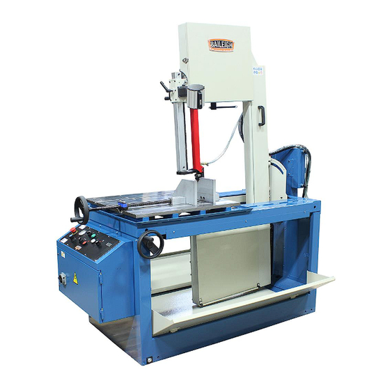
OPERATOR'S MANUAL
VERTICAL TILT BAND SAW
MODEL: BSVT-18P
Baileigh Industrial Holdings LLC
P.O. Box 531
Manitowoc, WI 54221-0531
Phone: 920.684.4990
Fax: 920.684.3944
sales@baileigh.com
REPRODUCTION OF THIS MANUAL IN ANY FORM WITHOUT WRITTEN APPROVAL OF BAILEIGH INDUSTRIAL
HOLDINGS LLC IS PROHIBITED. Baileigh Industrial Holdings LLC, Inc. does not assume and hereby disclaims any
liability for any damage or loss caused by an omission or error in this Operator's Manual, resulting from accident,
negligence, or other occurrence.
Rev. 11/2019
© 2019 Baileigh Industrial Holdings LLC
Advertisement
Table of Contents

Related Manuals for Baileigh Industrial BSVT-18P


Summary of Contents for Baileigh Industrial BSVT-18P
- Page 1 REPRODUCTION OF THIS MANUAL IN ANY FORM WITHOUT WRITTEN APPROVAL OF BAILEIGH INDUSTRIAL HOLDINGS LLC IS PROHIBITED. Baileigh Industrial Holdings LLC, Inc. does not assume and hereby disclaims any liability for any damage or loss caused by an omission or error in this Operator’s Manual, resulting from accident, negligence, or other occurrence.
-
Page 2: Table Of Contents
Table of Contents THANK YOU & WARRANTY ..................1 INTRODUCTION ......................3 GENERAL NOTES ......................3 SAFETY INSTRUCTIONS ....................4 SAFETY PRECAUTIONS ....................7 Dear Valued Customer: ....................7 TECHNICAL SPECIFICATIONS ..................9 TECHNICAL SUPPORT ....................10 UNPACKING AND CHECKING CONTENTS ..............11 TRANSPORTING AND LIFTING .................. - Page 3 PRE-OPERATION CHECKLIST ................... 40 Operation Procedure ....................40 Causes of Inaccurate Cutting ..................42 Clamping ........................42 LUBRICATION AND MAINTENANCE ................45 Lubrication ......................... 46 Hydraulic Oil / System ....................46 Oil Disposal ....................... 46 Accessing and Cleaning the Coolant System ............46 Oils for Lubricating Coolant ..................
-
Page 4: Thank You & Warranty
THANK YOU & WARRANTY Thank you for your purchase of a machine from Baileigh Industrial Holdings LLC. We hope that you find it productive and useful to you for a long time to come. Inspection & Acceptance. Buyer shall inspect all Goods within ten (10) days after receipt thereof. Buyer’s payment shall constitute final acceptance of the Goods and shall act as a waiver of the Buyer’s rights to inspect or... - Page 5 We apologize for any discrepancies that may occur. Baileigh Industrial Holdings LLC reserves the right to make any and all changes deemed necessary in the course of business including but not limited to pricing, product specifications, quantities, and product availability.
-
Page 6: Introduction
INTRODUCTION The quality and reliability of the components assembled on a Baileigh Industrial Holdings LLC machine guarantee near perfect functioning, free from problems, even under the most demanding working conditions. However, if a situation arises, refer to the manual first. If a solution cannot be found, contact the distributor where you purchased our product. -
Page 7: Safety Instructions
IMPORTANT PLEASE READ THIS OPERATORS MANUAL CAREFULLY It contains important safety information, instructions, and necessary operating procedures. The continual observance of these procedures will help increase your production and extend the life of the equipment. SAFETY INSTRUCTIONS LEARN TO RECOGNIZE SAFETY INFORMATION This is the safety alert symbol. - Page 8 SAVE THESE INSTRUCTIONS. Refer to them often and use them to instruct others. PROTECT EYES Wear safety glasses or suitable eye protection when working on or around machinery. PROTECT AGAINST NOISE Prolonged exposure to loud noise can cause impairment or loss of hearing.
- Page 9 BEWARE OF CUT AND PINCH POINTS Moving saw blade may result in loss of fingers or limb. DO NOT operate with guard removed. Follow lockout/tagout procedures before servicing. HIGH VOLTAGE USE CAUTION IN HIGH VOLTAGE AREAS. DO NOT assume the power to be off.
-
Page 10: Safety Precautions
SAFETY PRECAUTIONS Metal working can be dangerous if safe and proper operating procedures are not followed. As with all machinery, there are certain hazards involved with the operation of the product. Using the machine with respect and caution will considerably lessen the possibility of personal injury. However, if normal safety precautions are overlooked or ignored, personal injury to the operator may result. - Page 11 8. Do not force tool. Your machine will do a better and safer job if used as intended. DO NOT use inappropriate attachments in an attempt to exceed the machine’s rated capacity. 9. Use the right tool for the job. DO NOT attempt to force a small tool or attachment to do the work of a large industrial tool.
-
Page 12: Technical Specifications
TECHNICAL SPECIFICATIONS Capacity Rectangular 20" x 16.25” (508 x 412mm) Capacity Round 11.4" (289mm) Capacity 45° Right Tilt 13.89" x 16.25” (352.8 x 412mm) Capacity 45° Left Tilt 13.59" x 16.25” (345.1 x 412mm) Saw Bow Tilt (Left and Right, 45° – 0° – 45°) Miter Type Miter Operation Manual... -
Page 13: Technical Support
TECHNICAL SUPPORT Our technical support department can be reached at 920.684.4990 and asking for the support desk for purchased machines. Tech Support handles questions on machine setup, schematics, warranty issues, and individual parts needs: (other than die sets and blades). For specific application needs or future machine purchases contact the Sales Department at: sales@baileigh.com, Phone: 920.684.4990, or Fax: 920.684.3944. -
Page 14: Unpacking And Checking Contents
UNPACKING AND CHECKING CONTENTS Your Baileigh machine is shipped complete. Separate all parts from the packing material and check each item carefully. Make certain all items are accounted for before discarding any packing material. WARNING: SUFFOCATION HAZARD! Immediately discard any plastic bags and packing materials to eliminate choking and suffocation hazards to children and animals. -
Page 15: Transporting And Lifting
TRANSPORTING AND LIFTING NOTICE: Lifting and carrying operations should be carried out by skilled workers, such as a truck operator, crane operator, etc. If a crane is used to lift the machine, attach the lifting chain carefully, making sure the machine is well balanced. Follow these guidelines when lifting with truck or trolley: •... -
Page 16: Installation
• Check if the load is properly balanced by lifting it an inch or two. • Lift the machine, avoiding sudden accelerations or quick changes of direction. • Locate the machine where it is to be installed, then lower slowly until it touches the floor. INSTALLATION IMPORTANT: Consider the following when looking for a suitable location to place the machine:... -
Page 17: Anchoring The Machine
Anchoring the Machine • Once positioned, anchor the machine to the floor, as shown in the diagram. Use bolts and expansion plugs or sunken tie rods that connect through and are sized for the holes in the base of .31" the stand. -
Page 18: Overall Dimensions
OVERALL DIMENSIONS... -
Page 20: Assembly And Set Up
ASSEMBLY AND SET UP WARNING: For your own safety, DO NOT connect the machine to the power source until the machine is completely assembled and you read and understand the entire instruction manual. Stands 1. Position the saw in the desired location. 2. - Page 21 Air Supply 1. Using clean dry air regulated from 0.5 – 1.0CFM @ 80 – 100psi (.55 – .69MPa), supply air to the air filter through the 1/4” NPT inlet port. 2. Drain any accumulate moisture within the filter at least monthly.
-
Page 22: Getting To Know Your Machine
GETTING TO KNOW YOUR MACHINE... - Page 23 Item Description Function Main Disconnect Switch Turn this switch to power the machine on and off. Left Coolant Drip Tray Deflects coolant back to the reservoir. Uses coolant to spray and rinse saw chips into the base Coolant Rinse Hose. coolant tray to clear the cutting and clamping area of the saw and allow the chips to be collected for recycling.
-
Page 24: Electrical
3-phase power source other than direct 3-phase. If you are using an alternate power source, consult a certified electrician or contact Baileigh Industrial Holdings LLC prior to energizing the machine. CAUTION: HAVE ELECTRICAL UTILITIES CONNECTED TO MACHINE BY A CERTIFIED ELECTRICIAN! Check if the available power supply is the same as listed on the machine nameplate. - Page 25 WARNING: In all cases, make certain the receptacle in question is properly grounded. If you are not sure, have a qualified electrician check the receptacle • Improper connection of the equipment-grounding conductor can result in risk of electric shock. The conductor with insulation having an outer surface that is green with or without yellow stripes is the equipment-grounding conductor.
-
Page 26: Machine Setup And Adjustments
MACHINE SETUP AND ADJUSTMENTS Blade Changing Blade changes are periodically required when they become worn or to match the properties of varying materials. 1. Disconnect power to the machine. 2. Make certain the cutting head is locked in the vertical position. 3. -
Page 27: Blade Tracking Adjustment
8. Slide the blade on the wheels so the back edge of the blade is approximately 1/32" from the back flange of the wheel. Check the teeth on the portion of the blade between the upper and lower blade guides to see that they point down toward the table. -
Page 28: Saw Bow Tilt Adjustment
Saw Bow Tilt Adjustment The cutting head is adjustable to make angled cuts from -45° to +45°. Be sure the upper blade guide will clear any obstructions on the table before adjusting the cutting head angle. Detents are at each 15°. 1. - Page 29 8. Rotate the gib lock to lock the gib. The leadscrew will now be captured to allow for the handwheel to crank clamping pressure. 9. Make sure the work piece is secure before continuing. The work piece can be undamped by turning the hand wheel counterclockwise.
-
Page 30: Feeding Stroke
Feeding Stroke The cutting head can be fed forward or backward manually by rotating the feed handle counterclockwise or clockwise, respectively. The saw also can be fed forward automatically by adjusting the feed force knob clockwise until the desired feed is obtained. The stops will set a forward travel limit which will stop the blade and retract the saw bow to the start position. -
Page 31: Blade Speed Adjustment
Blade Speed Adjustment 1. Always set the feed force (A) to "O" before adjusting the blade speed. 2. The blade speed readout (B) on the control panel displays the blade speed in surface feet per minute. Choice of blade speed depends on the type and thickness of metal being cut. Refer to the chart below for recommended blade speeds. -
Page 32: Coolant Flow
Coolant flow Coolant is applied to the blade at the upper blade guide where a valve regulates the amount of flow to the blade. To enable or disable the coolant flow, set the coolant switch to "I" (ON) or "O" (OFF). GuidePost The guidepost assembly serves two purposes. -
Page 33: Adjusting The Blade Guides
Adjusting the Blade Guides The guide bearings are mounted on an eccentric shaft which is used to apply the guide pressure to the side of the band saw blade to hold the blade in a straight line within the cut window of the blade. -
Page 34: Before Each Use
BEFORE EACH USE • For dusty operations, wear a face shield along with safety goggles. • It is important to choose the right blade for the material and the type of cutting you plan to do. This saw is equipped with a bi-metallic blade which can be used to cut stainless steel, steel, iron, brass, aluminum, wood, plastic. -
Page 35: Breaking In A Band Saw Blade
• Curly Silvery and Warm Chips – optimum feed rate and saw speed Baileigh Industrial offers a wide selection of tooth styles for various cutting applications. Please phone Baileigh Industrial at (920.684.4990) or fax to (920.684.3944) to have one of our... -
Page 36: Blade Terminology
Blade Terminology The widest part of the blade measured from the back edge of the BLADE WIDTH blade to the tip of the tooth. GULLET DEPTH The distance from the tooth tip to the bottom of the curved area. The angle of the tooth face from a line perpendicular to the length TOOTH RAKE of the blade. -
Page 37: Blade Structure
Blade structure Bi-metal blades are the most commonly used. They consist of a silicon-steel blade backing by a laser welded high speed steel (HHS) cutting edge. The type of stocks are classified in M2, M42, M51 and differ from each other because of their major hardness due to the increasing percentage of Cobalt (Cc) and molybdenum (Mo) contained in the metal alloy. -
Page 38: Sets
COMBO TOOTH: 9° - 10° positive rake. This type of blade is the most suitable for the cutting of section bars and large and thick pipes as well as for the cutting of solid bars at maximum machine capacity. Available pitches: 3-4/4-6. SETS Saw teeth bent out of the plane of the saw body, resulting in a wide cut in the workpiece. -
Page 39: Blade Care
BLADE CARE The bandsaw blade is subjected to a tremendous amount of strain. Make sure to always use the appropriate feed rate for the type material you are cutting. Be sure to select a blade of the proper width, style, and pitch that will produce the best cut in your material. -
Page 41: Blade Breakage
BLADE BREAKAGE In some cases blade breakage is unavoidable due to the stresses that are imparted on the blade. Avoidable breakage is often the result of poor care, or poor operator judgment when it comes to adjusting or mounting the blade or blade guides. Listed below are some of the more common reasons for blade breakage. -
Page 42: Operation
OPERATION CAUTION: • Always wear proper eye protection with side shields, safety footwear, and leather gloves to protect from burrs and sharp edges. • Avoid accidental starting. Make sure the main disconnect switch is off before connection to a power source. •... -
Page 43: Pre-Operation Checklist
PRE-OPERATION CHECKLIST The following items should be checked at the beginning of each shift and by each new operator. This checklist is designed to maintain peak saw performance, increase blade life, reduce saw repairs, and provide a safe machine for the operator. •... - Page 44 5. Determine the angle of the cut. Use the lock lever to loosen the saw bow and manually tilt the bow from 45° left tilt to 45° right tilt. Never rely solely on the scale markers for the correct tilt angle. Always verify the angle with a protractor. 6.
-
Page 45: Causes Of Inaccurate Cutting
Causes of Inaccurate Cutting • Worn or mis-adjusted blade brush. • Dull blade. • Debris under the stock being cut. • Incorrect feed rate or feed pressure settings or excessive or rapid adjusting of these settings while the cut is being made. IMPORTANT: Do not allow excessive metal chips to buildup in the pan. - Page 46 CUTTING RATE CONTROL Cutting rate is defined as the number of square inches of material cut in a minute. The cutting rate is influenced by your choice of bandsaw blade, your cutting fluid, the blade speed selected, the feed pressure selected, the feed rate selected as well as the size, shape and machinability of the material you are cutting.
- Page 47 Once the feed pressure has been set, you should then set the feed rate. The location on the operator’s control panel of the machine. This control regulates the maximum speed at which the blade will move forward under a given pressure. In general, this should be set to move at a rate of 7 to 10 linear inches of travel when there is no material in the saw.
-
Page 48: Lubrication And Maintenance
LUBRICATION AND MAINTENANCE WARNING: Make sure the electrical disconnect is OFF before working on the machine. Maintenance should be performed on a regular basis by qualified personnel. Always follow proper safety precautions when working on or around any machinery. The maintenance jobs are listed below, divided into daily, weekly, and monthly intervals. If the following operations are neglected, the result will be premature wear of the machine and poor performance. -
Page 49: Lubrication
Lubrication AII ball bearings are permanently lubricated and sealed. They require no further lubrication. Hydraulic Oil / System The hydraulic oil is the primary medium for transmitting pressure and must lubricate the running parts of the pump. 1. Use hydraulic oil #68 SHELL BRAND or an equivalent with similar specifications. 2. -
Page 50: Bow Tilt Tension Adjustment
Bow Tilt Tension Adjustment The springs used to assist with tilting the saw bow may be adjusted to provide more or less tension to help support the saw bow during the tilting function. To much tension may prevent the bow from tilting to the full angle. -
Page 51: Electrical Diagram
ELECTRICAL DIAGRAM... -
Page 52: Pnuematic / Hydraulic Diagram
PNUEMATIC / HYDRAULIC DIAGRAM... - Page 53 NOTES...
- Page 54 NOTES...
- Page 55 NOTES...
- Page 56 BAILEIGH INDUSTRIAL HOLDINGS LLC 1625 D , WI 54220 UFEK RIVE ANITOWOC : 920. 684. 4990 F : 920. 684. 3944 HONE www.baileigh.com BAILEIGH INDUSTRIAL HOLDINGS LTD. U WIFT OINT WIFT ALLEY NDUSTRIAL STATE UGBY , CV21 1QH U IDLANDS...
Need help?
Do you have a question about the BSVT-18P and is the answer not in the manual?
Questions and answers