Table of Contents
Advertisement
Quick Links
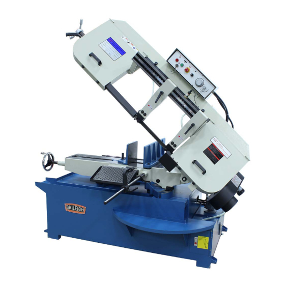
OPERATOR'S MANUAL
HORIZONTAL BAND SAW
MODEL: BS-330M
Baileigh Industrial
P.O. Box 531
Manitowoc, WI 54221-0531
Phone: 920.684.4990
Fax: 920.684.3944
Baileigh-Sales@jpwindustries.com
REPRODUCTION OF THIS MANUAL IN ANY FORM WITHOUT WRITTEN APPROVAL OF BAILEIGH INDUSTRIAL IS
PROHIBITED. Baileigh Industrial does not assume and hereby disclaims any liability for any damage or loss caused
by an omission or error in this Operator's Manual, resulting from accident, negligence, or other occurrence.
Edition 2 03/2023
Advertisement
Table of Contents

Related Manuals for Baileigh Industrial BS-330M


Summary of Contents for Baileigh Industrial BS-330M
- Page 1 REPRODUCTION OF THIS MANUAL IN ANY FORM WITHOUT WRITTEN APPROVAL OF BAILEIGH INDUSTRIAL IS PROHIBITED. Baileigh Industrial does not assume and hereby disclaims any liability for any damage or loss caused by an omission or error in this Operator’s Manual, resulting from accident, negligence, or other occurrence.
-
Page 2: Table Of Contents
Table of Contents THANK YOU & WARRANTY ................... 1 INTRODUCTION ......................3 GENERAL NOTES ......................3 SAFETY INSTRUCTIONS ....................4 SAFETY PRECAUTIONS ....................6 Dear Valued Customer: ....................6 TECHNICAL SPECIFICATIONS ..................9 TECHNICAL SUPPORT ....................9 UNPACKING AND CHECKING CONTENTS ..............10 TRANSPORTING AND LIFTING ................... - Page 3 Adjusting Blade Speed ....................35 ADJUSTMENTS ......................36 Adjusting Vise Square to the Blade ................36 Vise and Angle Cutting Adjustment ................36 Down-Bow Dampener ....................37 Thrust Roller Adjustment .................... 37 Guide Roller Adjustment ..................... 37 Changing Blades ......................39 Blade Tracking Adjustment ..................
-
Page 4: Thank You & Warranty
THANK YOU & WARRANTY Thank you for your purchase of a machine from Baileigh Industrial. We hope that you find it productive and useful to you for a long time to come. Inspection & Acceptance. Buyer shall inspect all Goods within ten (10) days after receipt thereof. Buyer’s payment shall constitute final acceptance of the Goods and shall act as a waiver of the Buyer’s rights to inspect or reject the... - Page 5 Baileigh Industrial makes every effort to ensure that our posted specifications, images, pricing and product availability are as correct and timely as possible. We apologize for any discrepancies that may occur. Baileigh Industrial reserves the right to make any and all changes deemed necessary in the course of business including but not limited to pricing, product specifications, quantities, and product availability.
-
Page 6: Introduction
After receiving your equipment remove the protective container. Do a complete visual inspection, and if damage is noted, photograph it for insurance claims and contact your carrier at once, requesting inspection. Also contact Baileigh Industrial and inform them of the unexpected occurrence. Temporarily suspend installation. -
Page 7: Safety Instructions
IMPORTANT PLEASE READ THIS OPERATORS MANUAL CAREFULLY It contains important safety information, instructions, and necessary operating procedures. The continual observance of these procedures will help increase your production and extend the life of the equipment. SAFETY INSTRUCTIONS LEARN TO RECOGNIZE SAFETY INFORMATION This is the safety alert symbol. - Page 8 SAVE THESE INSTRUCTIONS. Refer to them often and use them to instruct others. PROTECT EYES Wear safety glasses or suitable eye protection when working on or around machinery. PROTECT AGAINST NOISE Prolonged exposure to loud noise can cause impairment or loss of hearing.
-
Page 9: Safety Precautions
SAFETY PRECAUTIONS Metal working can be dangerous if safe and proper operating procedures are not followed. As with all machinery, there are certain hazards involved with the operation of the product. Using the machine with respect and caution will considerably lessen the possibility of personal injury. However, if normal safety precautions are overlooked or ignored, personal injury may result. - Page 10 9. Use the right tool for the job. DO NOT attempt to force a small tool or attachment to do the work of a large industrial tool. DO NOT use a tool for a purpose for which it was not intended.
- Page 11 WARNING: This product can expose you to chemicals including titanium dioxide which is known to the State of California to cause cancer, and lead which is known to the State of California to cause cancer and birth defects or other reproductive harm.
-
Page 12: Technical Specifications
TECHNICAL SPECIFICATIONS Capacity Rectangular 90° - 45° 13” x 18.9” / 11” x 10” (330 x 480 / 279 x 254mm) Capacity Round 90° - 45° 13” x 10” (330 x 255mm) Capacity Square 90° - 45° 13” x 10” (330 x 255mm) Return Manual Table Height... -
Page 13: Unpacking And Checking Contents
UNPACKING AND CHECKING CONTENTS Your Baileigh machine is shipped complete. Separate all parts from the packing material and check each item carefully. Make certain all items are accounted for before discarding any packing material. WARNING: SUFFOCATION HAZARD! Immediately discard any plastic bags and packing materials to eliminate choking and suffocation hazards to children and animals. -
Page 14: Transporting And Lifting
TRANSPORTING AND LIFTING NOTICE: Lifting and carrying operations should be carried out by skilled workers, such as a truck operator, crane operator, etc. If a crane is used to lift the machine, attach the lifting chain carefully, making sure the machine is well balanced. Follow these guidelines when lifting with truck or trolley: •... -
Page 15: Installation
INSTALLATION IMPORTANT: Consider the following when looking for a suitable location to place the machine: • Overall weight of the machine. • Weight of material being processed. • Sizes of material to be processed through the machine. • Space needed for auxiliary stands, work tables, or other machinery. •... -
Page 16: Anchoring The Machine
Anchoring the Machine • Once positioned, anchor the machine to the floor, as shown in the diagram. Use bolts and expansion plugs or sunken tie rods .31" that connect through and are sized for the holes in the base of (7.87mm) the stand. -
Page 17: Description Of Machine Parts
DESCRIPTION OF MACHINE PARTS... - Page 18 Item Description Function Supports the saw and houses the electrical enclosure and Saw Base coolant tank Vise Hand Wheel Opens and closes the vise jaws Vise Ratchet Allows for quick adjustment of the vise jaws Vise Jaws Clamp material to be cut 2 sets, Leading and trailing, guide the blade through the cut Blade Guide Rollers to hold the blade straight...
-
Page 19: Chip Brush
Chip Brush The chip brush may need periodic adjustment due to normal every day wear. 1. Disconnect machine from the power source 2. Open the right side wheel cover. 3. Loosen bolts (A). 4. Raise the chip brush so that it touches the blade. 5. -
Page 20: Water Gun Operation
Water Gun Operation Water gun is designed for washing off the chips and debris in or on the work table, as well as, being used during machine operation. 1. Open the access door and remove the spray hose. 2. Press the operation start button to start machine. 3. -
Page 21: Assembly And Set Up
ASSEMBLY AND SET UP WARNING: For your own safety, DO NOT connect the machine to the power source until the machine is completely assembled and you read and understand the entire instruction manual. Drip Tray 1. Unwrap the drip tray and position at the front of the saw. 2. - Page 22 Material Stop 1. Unwrap the material stop parts. 2. Loosen the two set screws (A) on the hinge assembly. 3. Insert the stop rod into the hinge assembly so that the flat surface with the scale is up and the two detents (B) align with the set screws.
- Page 23 Laser Guide Aiming The laser will project a long thin line down to the cut point of the blade to assist in positioning of the material for the cut. This line is typically positioned (aimed) to indicate the front edge of the blade. Aiming is done by rotating the laser within the extension arm so that the line matches the line of the blade, and by tilting so that the line is visible at the very front edge...
-
Page 24: Electrical
ELECTRICAL WARNING: Baileigh Industrial is not responsible for any damage caused by wiring up to an alternative 3-phase power source other than direct 3-phase. If you are using an alternate power source, consult a certified electrician or contact Baileigh Industrial prior to energizing the machine. -
Page 25: Plug Connection
WARNING: In all cases, make certain the receptacle in question is properly grounded. If you are not sure, have a qualified electrician check the receptacle • Improper connection of the equipment-grounding conductor can result in risk of electric shock. The conductor with insulation having an outer surface that is green with or without yellow stripes is the equipment-grounding conductor. -
Page 26: Before Each Use
BEFORE EACH USE • For dusty operations, wear a face shield along with safety goggles. • It is important to choose the right blade for the material and the type of cutting you plan to do. This saw is equipped with a bi-metallic blade which can be used to cut stainless steel, steel, iron, brass, aluminum, wood, plastic. -
Page 27: Breaking In A Band Saw Blade
• Curly Silvery and Warm Chips – optimum feed rate and saw speed Baileigh Industrial offers a wide selection of tooth styles for various cutting applications. Please phone Baileigh Industrial at (920.684.4990) or fax to (920.684.3944) to have one of our... -
Page 28: Blade Terminology
Blade Terminology The widest part of the blade measured from the back edge of the BLADE WIDTH blade to the tip of the tooth. GULLET DEPTH The distance from the tooth tip to the bottom of the curved area. The angle of the tooth face from a line perpendicular to the length TOOTH RAKE of the blade. -
Page 29: Blade Structure
Blade structure Bi-metal blades are the most commonly used. They consist of a silicon-steel blade backing by a laser welded high speed steel (HHS) cutting edge. The type of stocks are classified in M2, M42, M51 and differ from each other because of their major hardness due to the increasing percentage of Cobalt (Cc) and molybdenum (Mo) contained in the metal alloy. -
Page 30: Sets
COMBO TOOTH: 9° - 10° positive rake. This type of blade is the most suitable for the cutting of section bars and large and thick pipes as well as for the cutting of solid bars at maximum machine capacity. Available pitches: 3-4/4-6. SETS Saw teeth bent out of the plane of the saw body, resulting in a wide cut in the workpiece. -
Page 31: Blade Care
BLADE CARE The bandsaw blade is subjected to a tremendous amount of strain. Make sure to always use the appropriate feed rate for the type material you are cutting. Be sure to select a blade of the proper width, style, and pitch that will produce the best cut in your material. -
Page 33: Blade Selection
Blade Selection Material <3mm >5mm >50mm >100mm >150mm >200mm <0.12” >0.2” >2” >4” >6” >8” Sawblade • (HSS) 14T • (HSS) 6/10T • (HSS) 5/8T • • (HSS) 4/6T • (HSS) 3/4T • • (HSS) 2/3T • (HSS) 1/2T • (HCS) 10T •... -
Page 34: Blade Breakage
BLADE BREAKAGE In some cases blade breakage is unavoidable due to the stresses that are imparted on the blade. Avoidable breakage is often the result of poor care, or poor operator judgment when it comes to adjusting or mounting the blade or blade guides. Listed below are some of the more common reasons for blade breakage. -
Page 35: Operation
OPERATION CAUTION: Always wear proper eye protection with side shields, safety footwear, and leather gloves to protect from burrs and sharp edges. When handling large heavy materials make sure they are properly supported. NEVER operate saw without blade guards in place. General Operating Instructions 1. -
Page 36: Setting Up The Machine For Operation
Setting Up the Machine for Operation 1. Select the proper speed and blade for the type of material you are going to cut. 2. Make sure blade tension is adjusted properly. 3. Lift the saw bow up and turn OFF the descent ON/OFF valve (A). -
Page 37: Vise Adjustment
Vise Adjustment To position the moveable vise jaw: 1. Turn vise handwheel (A) 1/2 turn counter- clockwise. 2. Move rack block (B) to desired location by sliding along the bed. Place the rack block latch onto the rack. 3. Turn the handwheel to tighten the vise. To adjust the vise for angle cutting: 4. -
Page 38: Work Stop-Bar Adjustment
Work Stop-Bar Adjustment The stop bar can be adjusted during angle cutting, and the procedure is as follows: 1. Unfasten the handle (A), and use a hex wrench (allen wrench) to loosen the hex socket set screw (B). 2. Push the bar gradually to the right side to get the desired angle and then tighten the set screw (B) and handle (A). -
Page 39: Adjustments
ADJUSTMENTS WARNING: Disconnect the machine from the power source before making any adjustments or repairs! Failure to comply may result in serious injury! Adjusting Vise Square to the Blade 1. Disconnect the machine from the power source. 2. Place a machinist's square on the table against the blade and the vise (fixed). The Square should lie along the entire length of the vise and blade without any gaps. -
Page 40: Down-Bow Dampener
Down-Bow Dampener The dampener (A) functions to produce a finer cut by reducing the rate of bow descent as the blade nears the table. The width of measurements of the blades between inch size and mm size are slightly different. This saw is equipped with inch size blade at the factory. - Page 41 Note: The blade should travel freely up and down between the ball bearings. Do not pinch the blade. 5. Tighten locking screws (A). 6. Adjust the blade guides back into contact with blade and tighten thumb screw and hex socket cap screw (E).
-
Page 42: Changing Blades
Changing Blades WARNING: Disconnect the machine from the power source before making any adjustments or repairs! Failure to comply may result in serious injury! 1. Raise the saw arm approximately 6” (150mm). Press the emergency stop to hold the arm in place. -
Page 43: Blade Tracking Adjustment
11. When you are sure the back of the blade is against the wheel flanges of both wheels and properly inserted into the guides, finish putting tension on the blade. 12. Proper tension is achieved when the pointer is on the inner mark of the blade tension scale (F) behind the fly wheel. -
Page 44: Automatic Shut-Off Adjustment
5. Loosen the three bolts (A) located on the top of the tacking nuts. 6. Tracking adjustment is accomplished by either loosening or tightening three adjusting nuts (B). 7. Tracking is set properly when the back of the blade lightly touches the wheel flange. Note: Over-tracking (allowing blade back to rub hard against wheel flange) will damage the blade wheels and blade. -
Page 45: Lubrication And Maintenance
LUBRICATION AND MAINTENANCE WARNING: Make sure the electrical disconnect is OFF before working on the machine. Maintenance should be performed on a regular basis by qualified personnel. Always follow proper safety precautions when working on or around any machinery. The maintenance jobs are listed below, divided into daily, weekly, and monthly intervals. If these operations are neglected, the result will be premature wear and poor performance. -
Page 46: Lubrication
Lubrication AII ball bearings are permanently lubricated and sealed. They require no further lubrication. Replacing the Coolant 1. Disconnect the machine from the power source. 2. Remove the drain plug (A) with a hex wrench and allow coolant to drain completely. 3. -
Page 47: Storing Machine For Extended Period Of Time
5. Verify that the oil level reaches dot in middle of sight glass. 6. Replace filler cap. 7. Connect machine to the power source. 8. Use a light machine oil to lubricate all other moving parts as needed. Storing Machine for Extended Period of Time If this machine is to be inactive for a long period of time, prepare the machine as follows: •... -
Page 48: Electrical Panel Layout
ELECTRICAL PANEL LAYOUT... -
Page 49: Electrical Schematic
ELECTRICAL SCHEMATIC... -
Page 50: Parts Diagram
PARTS DIAGRAM... -
Page 52: Parts List
Parts List Item Part No. Description Size No. Qty. BS330M-1 Base TS-1499141 Hex. Cap Bolt M12x80 TS-2342121 BS330M-4 Coolant Pump TS-1534051 Round Head Screw M6x16 TS-1524021 Set Screw M8x10 TS-2286121 Round Head Screw M6x12 TS-2361061 Spring Washer TS-1550041 Washer BS330M-6-4 Coolant Tank Cover BS330M-7 BS330M-7-3... - Page 53 Item Part No. Description Size No. Qty. 14-2 BS330M-14-2 Hinge Pin 14-4 TS-2286302 Round Head Screw M6x30 14-5 TS-2361061 Spring Washer 14-6 TS-1550041 Washer 14-7 TS-1541021 BS330M-20 Lead Screw Seat 20-1 TS-0270032 Hex. Cap Screw M8x30 20-2 TS-2361081 Spring Washer 20-3 TS-1550061 Washer...
- Page 54 Item Part No. Description Size No. Qty. BS330M-33 Pivot Bracket 33-1 BS330M-33-1 Wire Plate 33-2 TS-2361101 Spring Washer 33-3 TS-1505061 Hex. Cap Bolt M10x40 33-4 BS330M-33-4 Steel Wire 33-5 BS330M-33-5 Wire Clip 33-6 BS330M-33-6 Spring 33-7 BS330M-33-7 Adjustable C-Bolt 33-8 TS-0640111 1/2”...
- Page 55 Item Part No. Description Size No. Qty. BS330M-51 Cylinder Assembly 51-1 BS330M-51-1 Holder BS330M-52 Lock Pin BS330M-53 Top Mounting Plate TS-1492031 Hex. Cap Bolt M12x35 TS-2361011 Spring Washer BS330M-63 Contactor (main motor) 63-1 BS330M-63-1 Overload Relay 63-2 BS330M-63-2 Contactor (pump) BS330M-64 Fuse BS330M-65...
- Page 56 Item Part No. Description Size No. Qty. 84-2 TS-2360121 Washer 84-3 BS330M-84-3 Bushing BS330M-85 Saw Blade BS330M-86 Knob 1/4x3/8 TS-1491041 Hex. Cap Bolt M10x30 TS-2361101 Spring Washer TS-1492031 Hex. Cap Bolt M12x35 TS-2361121 Spring Washer BS330M-91 Blade Guide BS330M-92 Saw Arm 92-1 BS330M-92-1 92-2...
- Page 57 Item Part No. Description Size No. Qty. V100-2 TS-2361081 Spring Washer V100-3 TS-1550061 Washer V101 BS330M-V101 Shaft V101-1 BS330M-V101-1 Knob V101-2 TS-0680032 Washer 5/16” V101-3 TS-0561021 5/16” V101-4 TS-0733051 Spring Washer 5/16” BS330M-102 Guide Bracket-Left TS-1524041 Set Screw M8x16 BS330M-104 Blade Guide-Left BS330M-105 Blade Guide-Right...
- Page 58 Item Part No. Description Size No. Qty. 125-2 TS-2361081 Spring Washer 125-3 TS-1550061 Washer BS330M-126 Adjusting Bracket Mount-Right 126-1 BS330M-126-1 Adjusting Bracket Mount-Left BS330M-127 Lock Block BS330M-128 Handle 3/8x1-1/2 TS-1550071 Washer TS-1505061 Hex. Socket Cap Screw M10x40 TS-2361101 Spring Washer TS-1550071 Washer TS-1506021...
- Page 59 Item Part No. Description Size No. Qty. 149-2 TS-2361061 Spring Washer 149-3 TS-1550041 Washer BS330M-150 Electrical Box 150-1 TS-1482021 Hex. Cap Bolt M6x12 150-2 TS-2361061 Spring Washer 150-3 TS-1550041 Washer BS330M-151 Control Panel 151-1 TS-1534041 Round Head Screw M5x10 BS330M-152 Relief Valve Assembly BS330M-153 Power Indicator Light...
- Page 60 Item Part No. Description Size No. Qty. 172-1 TS-1533032 Round Head Screw M5x10 BS330M-173 Spring Supporting Shaft BS330M-174 Belleville Spring W=2.5mm 180A BS330M-180A Eccentric Sleeve Assembly 180B BS330M-180B Sleeve Assembly BS330M-185 Laser Bracket (Lower) BS330M-186 Laser Block TS-1503071 Hex. Socket Cap Screw M6x30 TS-2361061 Spring Washer...
- Page 61 Item Part No. Description Size No. Qty. TS-1524021 Set Screw M8x10 BS330M-213 Bracket TS-1503071 Hex. Socket Cap Screw M6x30 TS-2311101 TS-1491041 Hex. Cap Bolt M10x30 BS330M-241 Turning Slide (Short) BS330M-242 Washer Ø51x5x13 BS330M-243 Hex. Cap Bolt M12x20 TS-2360121 Washer TS-1506031 Hex.
- Page 62 Item Part No. Description Size No. Qty. TS-1524021 Set Screw M8x10 BS330M-278 Chip Grate 278-1 TS-1491021 Hex. Cap Bolt M10x20 278-2 TS-2361101 Spring Washer 278-3 TS-1550071 Washer...
-
Page 63: Troubleshooting
TROUBLESHOOTING WARNING: Make sure the electrical disconnect is OFF before working on the machine. SYMPTOM POSSIBLE CAUSE (S) CORRECTIVE ACTION 1. Actuator on cylinder does not Saw Motor Does Not contact switch properly. 1. Re-adjust actuator or switch. Stop When Cut is 2. - Page 64 1. Blade guides worn 2. Blade guide bearings not 1. Replace Unusual Wear on adjusted properly 2. Adjust as per operator’s manual Side/Back of Blade 3. Blade guide bearing bracket is 3. Tighten loose 1. Use finer tooth blade 1. Teeth too coarse for work 2.
- Page 65 NOTES...
- Page 66 NOTES...
- Page 67 NOTES...
- Page 68 BAILEIGH INDUSTRIAL 1625 D , WI 54220 UFEK RIVE ANITOWOC : 920. 684. 4990 F : 920. 684. 3944 HONE www.baileigh.com...