AGA Elise Owner's Manual
48 induction
Hide thumbs
Also See for Elise:
- Owner's manual (52 pages) ,
- Service manual (64 pages) ,
- Owner's manual (52 pages)

Subscribe to Our Youtube Channel
Related Manuals for AGA Elise


Summary of Contents for AGA Elise
- Page 1 48 Induction Owner’s Guide User & Installation Instructions READ THESE INSTRUCTIONS FULLY BEFORE USE SAVE THESE INSTRUCTIONS FOR FUTURE REFERENCE U110700 - 01...
- Page 2 WARNING! The anti-tip device supplied with this range must be installed when the appliance is installed. This will reduce risk of tipping of the appliance from abnormal usage or by excessive loading of the oven door. WARNING! • ALL RANGES CAN TIP. A CHILD OR ADULT CAN TIP THE RANGE AND BE KILLED. •...
-
Page 3: Table Of Contents
Contents Important Safety Information Cooker Overview Cooking Tips Cooking Table Cleaning Your Range Troubleshooting Service and Parts Installation Safety Instructions 10. Fitting the Flue, Flue Vent and Side Panels 11. Removing the Side Panels 12. Electrical Connection 13. Final Fitting 14. -
Page 4: Important Safety Information
1. Important Safety Information To Prevent Fire or Smoke Damage Have your appliance properly installed and grounded by a qualified technician. The installation must conform with local Before using the range make sure all the packing materials codes or, in the absence of local codes, in accordance with have been removed. -
Page 5: Wear Suitable Clothing
to tip, resulting in serious burns or other injury. Teach them Wear Suitable Clothing not to play with controls or any other part of the range. Never wear loose-fitting or hanging clothes while using the Never store items of interest to children in the ... -
Page 6: Use The Right Size Pan
Use the Right Size Pan In the interests of hygiene and safety the range should be kept clean at all times as a build up in fats and other food This appliance is equipped with cooktop zones of different stuff could result in a fire. sizes. -
Page 7: Cooker Overview
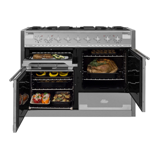
2. Cooker Overview Fig. 2.1 ArtNo.215-0009 - 110 Elan DF The 48” induction range (Fig. 2.1) has the following features: Fig. 2.2 5 induction cooking zones A control panel A glide-out broiler system Main multi-function oven Convection oven Storage drawer The Cooktop ArtNo.110-0045 - 120DF - Mercury door clearances Use only pans that are suitable for induction cooktops. - Page 8 The very best pans have bases that are very slightly curved Fig. 2.4 up when cold (Fig. 2.4). If you hold a ruler across the bottom you will see a small gap in the middle. When they heat up the metal expands and lies flat on the cooking surface.
- Page 9 (60 °C) and may still cause burns. Once the temperature has Auomatic Heat-up Time at Power level dropped to below 140 °F (60 °C) the [ H ] will go out. 100% (min:sec) 0:48 Automatic Heat-up, A 2:24 This function is available on all of the cooking zones. It allows rapid heating to bring the selected cooking zone up 3:50 to temperature.
- Page 10 • L2 will maintain a temperature of about 194 °F (90 °C) – ideal for simmering (bring the pan to the boil and then Maximum Operating Time Power Level select L2 to keep soups, sauces, stews, etc at an optimal 2 hours simmer).
- Page 11 Glide Out Broiler System™ Fig. 2.10 NEVER operate the broiler with the door closed. Open the door and pull the broiler pan carriage forward using the handle (Fig. 2.10). The broiler has two elements that allow either the whole area of the pan to be heated or just the right- hand half.
- Page 12 Ovens throughout the oven, allowing you to cook large amounts quickly. Please refer to Fig. 2.1. Convection cooking is particularly suitable for batch baking References to ‘left-hand’ and ‘right-hand’ ovens apply as on several shelves at one time and is a good ‘all-round’ viewed from the front of the appliance.
-
Page 13: Convection Oven
Browning Element Function This function uses the element in the top of the oven Defrost To thaw small items in the oven without heat only. It is a useful function for the browning or finishing of pasta dishes, vegetables in sauce, A full cooking function, even heat throughout, Convection oven shepherds pie and lasagne, the item to be browned being... -
Page 14: Oven Shelves
Accessories Fig. 2.17 Fig. 2.18 Oven Shelves The range is supplied with the following: • 2 standard shelves (Fig. 2.17) • 1 drop shelf (Fig. 2.18) • 2 telescopic shelf with runners (Fig. 2.19) • 2 sets of side supports (Fig. 2.20) Fig. - Page 15 To Remove and Fit a Shelf to the Side Supports Fig. 2.24 The shelf has a small kink on either side (Fig. 2.24). To remove the shelf, line these up with the stops in the shelf support (Fig. 2.25). Lift the rear of the shelf upward so that it will pass over the shelf stop and then pull it forward (Fig.
-
Page 16: Cooking Tips
3. Cooking Tips Cooking with a Multi-function Oven When the oven is on, DO NOT leave the door open for longer than necessary, otherwise the knobs may get very hot. REMEMBER: not all modes are suitable for all food types. The •... -
Page 17: Cooking Table
4. Cooking Table DocNo.031-0004 - Cooking table - electric & fan single cavity The oven control settings and cooking times given in the table below are intended to be used as a guide only. Individual tastes may require the temperature to be altered to provide a preferred result. ArtNo.050-0019 - Albertine SC Food is cooked at lower temperature in a fan oven than in a conventional oven. -
Page 18: Cleaning Your Range
Daily Care First of all make sure that all heat indicator lights are off and that the cooking surface is cool. Apply a small dab of AGA Ceramic Hob Cleaner (SAG-W2022) in the centre of each area to be cleaned. Dampen a clean paper towel and work the cream onto the cooking surface. -
Page 19: Control Panel And Oven Doors
Control Panel and Oven Doors Fig. 5.1 Avoid using any abrasive cleaners including cream cleaners, on brushed stainless steel surfaces. For best results use liquid detergents. The control panel and control knobs should only be cleaned with a soft cloth wrung out in clean hot soapy water – but take care that no surplus water seeps into the appliance. - Page 20 Once you have finished, hook the side rails back onto Fig. 5.5 the sides of the chamber. Pull the telescopic rails out and fit the broiler tray onto them, making sure to locate the cut-outs onto the telescopic runner tabs (Fig. 5.5). Replace the broiler pan.
-
Page 21: Cleaning Table
Enamel or paint stubborn stains, remove with gentle Door, door surround and storage drawer detergent. exterior Use AGA Chrome & Steel Cleaner and Stainless steel buff with a microfiber cloth. Hot soapy water, soft cloth. AGA Enamel Sides and plinth Painted surface Cleaner or AGA Chrome &... -
Page 22: Troubleshooting
6. Troubleshooting All servicing and repairs must be carried out by a Steam is coming from the oven qualified service engineer. When cooking foods with a high water content (e.g. Note: The induction cooktop is able to self-diagnose oven chips) there may be some steam visible at the rear a number of problems and can show this information grille. - Page 23 Check that the door seal is not damaged. Fig. 6.1 A dish of water when placed on the shelf should be the same depth all over. (For example, if it is deeper at the back, then the back of the range should be raised up or the front lowered.) If the range is not level arrange for your supplier to level it for you.
-
Page 24: Installation Instructions
INSTALLATION Check the appliance is electrically safe when you have finished. Installation Instructions READ THESE INSTRUCTIONS FULLY BEFORE USE SAVE THESE INSTRUCTIONS FOR FUTURE REFERENCE SAVE THE INSTALLATION INSTRUCTIONS FOR THE LOCAL ELECTRICAL INSPECTOR’S USE... - Page 25 INSTALLATION Check the appliance is electrically safe when you have finished. WARNING! The anti-tip device supplied with this range must be installed when the appliance is installed. This will reduce risk of tipping of the appliance from abnormal usage or by excessive loading of the oven door. WARNING! ...
-
Page 26: Service And Parts
If you are still having difficulty, please contact Tech Support at 800-223-3900 or email techsupport@agamarvel.com. Please Note For warranty information or to register your AGA range, go to www.aga-ranges.com. You may also refer to the warranty document provided with the appliance or contact Customer Service at 800-223-3900. -
Page 27: Installation Safety Instructions
Ensure all clearances are followed. Refer to positioning the range. Improper installation, adjustment, alteration, service or maintenance can cause injury or property damage. Refer to this manual. For assistance or additional information, consult a qualified, appointed AGA Service Agent. - Page 28 INSTALLATION Check the appliance is electrically safe when you have finished. Location of the Range Included Accessories: The range may be installed in a kitchen/kitchen dining area Broiler pan & trivet Broiler pan cradle but NOT in a room containing a bath or shower. The range is freestanding and should not be placed on a separate base.
-
Page 29: Positioning The Range
149°F/65°C above room Fig. 9.3 temperature. ArtNo.110-0064 - 110DF - Elise min positions above cooker Clearances to Combustibles Dimension Description Canada Gap between side of appliance and adjacent vertical surface ABOVE 1 3/16"... -
Page 30: Moving The Range
INSTALLATION Check the appliance is electrically safe when you have finished. The depth of the range is 27 ⁄ " (708 mm) overall (Fig. 9.4). Fig. 9.4 (1177mm) If the range is near a corner of the kitchen, a clearance of 3 ½” (90 mm) is required to allow the oven doors to open (708 mm) (Fig. -
Page 31: Fitting The Flue, Flue Vent And Side Panels
INSTALLATION Check the appliance is electrically safe when you have finished. 10. Fitting the Flue, Flue Vent and Side Panels Checking the Parts: Fig. 10.1 Flue Flue Vent Flue Fan Assembly Fig. 10.2 Fitting the Flue Remove the four screws from the broiler flue opening (Fig. - Page 32 INSTALLATION Check the appliance is electrically safe when you have finished. Fitting the Cooling Fan Box Fig. 10.3 Remove the six screws where the cooling fan box will be fixed Fig. 10.3. The shape of the molex plug should match the socket. Gently connect the molex plug to the molex connector socket Fig.
- Page 33 INSTALLATION Check the appliance is electrically safe when you have finished. Fitting the Side Panel Rear Checking the Parts: Retaining Brackets Side panel rear retaining Side panels brackets Located at the bottom left and right rear corner of the A051761 - Right-hand A052064 - Right-hand range, remove the two screws (Fig.
- Page 34 INSTALLATION Check the appliance is electrically safe when you have finished. Fitting the Side Panels Check everything is firmly connected and tighten the screw in the flue vent to secure the side panel in Loosen the screw in the flue vent (Fig. 10.10). position (Fig.
- Page 35 INSTALLATION Check the appliance is electrically safe when you have finished. Fitting the Front Mounting For safety’s sake make sure the drawer runners are out of the way. Brackets On the front of the range base there are two mounting Open the right-hand oven door and pull the drawer out plates.
- Page 36 INSTALLATION Check the appliance is electrically safe when you have finished. Fitting the Bottom Panel (Toe kick) Adjust the bottom panel to set the gap between the side panels and doors equally (Fig. 10.18). When it is Tilt the bottom of the panel slightly to locate the lower positioned correctly, use a suitable flat open-ended slots onto the washers (Fig.
- Page 37 INSTALLATION Check the appliance is electrically safe when you have finished. Fitting the Drawer Fig. 10.20 To fit the drawer, pull the side rails fully out (Fig. 10.20). Carefully move the drawer back between the rails and rest it on the side rails. At each side, hold the front of the drawer and pull the side rail forward so that the clips click into position, holding the drawer to the side rails (Fig.
-
Page 38: Completing The Move
INSTALLATION Check the appliance is electrically safe when you have finished. Fitting the Restraint Chain and Fig. 10.22 Anti-Tip Device Alternative positions A suitable anti-tip device is supplied and shown in for anti-tip device (Fig. 10.22). When fitting the anti-tip bracket (Fig. 10.22 and Fig. -
Page 39: Removing The Side Panels
INSTALLATION Check the appliance is electrically safe when you have finished. 11. Removing the Side Panels Removing the Bottom Panel Disconnect the electrical supply. (Plinth/Toekick) You will need the following equipment to remove the side panels: After removing the drawer open the left-hand oven •... - Page 40 INSTALLATION Check the appliance is electrically safe when you have finished. Removing the Side Panels Loosen one screw in the vent (Fig. 11.5). Push forward the side panel so that it moves away from the flue vent and the retaining washer (Fig. 11.6). Inside the top of the side panel top are two tabs.
-
Page 41: Electrical Connection
INSTALLATION Check the appliance is electrically safe when you have finished. 12. Electrical Connection Have your appliance properly installed and grounded by a Provide Proper Electrical Supply qualified technician. The installation must conform with local This range must be supplied with 240 V 60 Hz, and connected codes or in the absence of local codes in accordance with to an individual, properly grounded branch circuit protected the National Electrical Code NFPA 70 or the Canadian Electric... -
Page 42: Final Fitting
INSTALLATION Check the appliance is electrically safe when you have finished. 13. Final Fitting Cooktop Check Refer to Section 2, page 4 and check operation of each cooking zone in turn. Be sure to use pans of the correct size and material. -
Page 43: Circuit Diagram
14. Circuit Diagram Induction Unit P026819 P026819 P029549 P033458 P028728 P033458 LH Oven Control RH Oven Control Broiler Control Code Description Code Code Code Colour Right-hand oven thermostat Broiler Thermostat Blue Right-hand oven switch block Broiler Controller Brown Code Description Code Description Code... -
Page 44: Technical Data
15. Technical Data INSTALLER: Please leave these instructions with the user. Data plate DATA BADGE LOCATION: Inside base drawer of cavity. Remove the drawer. COUNTRY OF DESTINATION: USA, Canada, Mexico. Connections ArtNo280-0090 Drawer Cavity & Badges Electric Supply 240 V 60 Hz Electric Rating 240V (2 Wire + N + Grd), 60Hz, 18.5 kW * Branch Circuit Protection... -
Page 45: Consumer Warranty
AGA warrants the oven heating elements against defects in material or workmanship for an additional two years. These parts will be repaired or replaced at the option of AGA without charge, but you pay for labor and transportation subject to the terms and conditions set out below. - Page 46 Notes...
- Page 47 Notes...
- Page 48 Manufactured in the UK for: AGA Marvel 1260 E. VanDeinse St. Greenville, MI 48838 Business (616) 754-5601 Fax (616) 754-9690 Toll Free Telephone 800-223-3900 www.aga-ranges.com...
Need help?
Do you have a question about the Elise and is the answer not in the manual?
Questions and answers