Bender ISOMETER isoRW425 Manual
Insulation monitoring device
Hide thumbs
Also See for ISOMETER isoRW425:
- Manual (76 pages) ,
- Quick start manual (13 pages) ,
- Quick start manual (12 pages)

Related Manuals for Bender ISOMETER isoRW425


Summary of Contents for Bender ISOMETER isoRW425
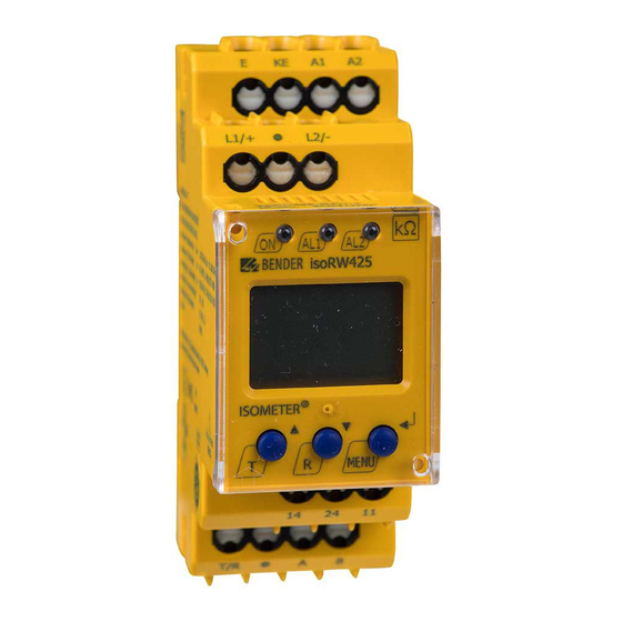
- Page 1 Manual EN ISOMETER® isoRW425 Insulation monitoring device for unearthed AC-, AC/DC and DC systems in railway applications up to 3(N)AC, AC/DC 440 V Software version: D0418 V2.xx isoRW425_D00052_06_M_XXEN/09.2023...
- Page 2 isoRW425_D00052_06_M_XXEN/09.2023...
-
Page 3: Table Of Contents
Indication of important instructions and information...............5 Signs and symbols............................5 Service and Support............................5 Training courses and seminars........................6 Delivery conditions............................6 Inspection, transport and storage......................6 Warranty and liability.............................6 Disposal of Bender devices..........................7 1.10 Safety..................................7 Function.......................8 Intended use..............................8 Device features..............................8 Functional description........................... 9 2.3.1... - Page 4 Table of contents Operating and display elements......................18 Menu overview...............................20 Displaying measured values........................21 Setting the response values (AL)......................22 4.4.1 Setting the response values for monitoring the insulation resistance (R mode) or the insulation impedance (Z mode).......................22 4.4.2 Setting the response values for undervoltage and overvoltage..........22 4.4.3 Response values overview.........................22 Configuring fault memory, alarm relays, and interfaces (out)............23...
-
Page 5: General Information
Protect from dust Temperature range Recycling RoHS directives Service and Support Information and contact details about customer service, repair service or field service for Bender devices are available on the following website: Fast assistance | Bender GmbH & Co. KG. isoRW425_D00052_06_M_XXEN/09.2023... -
Page 6: Training Courses And Seminars
Regular face-to-face or online seminars for customers and other interested parties: www.bender.de > know-how > seminars. Delivery conditions The conditions of sale and delivery set out by Bender GmbH & Co. KG apply. These can be obtained in printed or electronic format. The following applies to software products: ‘Software clause in respect of the licensing of standard software as part of deliveries,... -
Page 7: Disposal Of Bender Devices
ISOMETER® isoRW425 Disposal of Bender devices Abide by the national regulations and laws governing the disposal of this device. For more information on the disposal of Bender devices, refer to www.bender.de > service & support. 1.10 Safety If the device is used outside the Federal Republic of Germany, the applicable local standards and regulations must be complied with. -
Page 8: Function
• Two separately adjustable response value ranges from 1…990 k (prewarning, alarm) • RS-485 (galvanically isolated) including the following protocols: – BMS (Bender measuring device interface) for the data exchange with other Bender devices – Modbus RTU – IsoData (for continuous data output) •... -
Page 9: Functional Description
ISOMETER® isoRW425 Functional description The ISOMETER® measures the insulation resistance R and the system leakage capacitance C between the system to be monitored (L1/+, L2/–) and earth (PE). Z mode (selectable in the “SEt” menu) calculates the insulation impedance Z from R and C with a system frequency parameter f... -
Page 10: Monitoring Of The Insulation Impedance (Z Mode)
Function Each time the mode is switched from R mode to Z mode, parameters “R1” and “R2”, and hence the monitoring of the insulation resistance R will be deactivated. In Z mode the insulation impedance Z is the main measured value and the measured insulation resistance R may have increased tolerances depending on the system condition. - Page 11 ISOMETER® isoRW425 2.3.4.1 Error codes In the event of a device error the display shows the respective error code. Overview of some error codes Error code Meaning PE connection error The connection of “E” or “KE” to earth is interrupted. E.01 Action: Check connection, eliminate error.
-
Page 12: Malfunction
(“Err”) will be signalled, “E.xx” appears on the display as an identifier for error type xx, and the LEDs “ON”/“AL1”/“AL2” will flash. Please contact Bender Service, if the error occurs again after the device has been restarted or the factory settings have been restored. -
Page 13: Password Protection (On, Off)
ISOMETER® isoRW425 Example: A maximum permissible system leakage capacitance of C = 300 F and an insulation fault of = 2.5 k (R = 5 k ) in a DC 400 V system result in an operating time of t <... -
Page 14: 2.3.10 Fault Memory
The ISOMETER® uses the serial hardware interface RS-485 with the following protocols: • BMS The BMS protocol is an essential component of the Bender measuring device interface (BMS bus protocol). Data transmission generally makes use of ASCII characters. • Modbus RTU Modbus RTU is an application layer messaging protocol, and it provides master/slave communication between devices that are connected via bus systems and networks. -
Page 15: Installation, Connection And Commissioning
ISOMETER® isoRW425 Installation, connection and commissioning Dimensions 45 70.5 31.1 47.5 74.5 Figure: Dimension diagram (in mm) Installation Application in rail vehicles/DIN EN 45545-2:2016 If the distance to neighbouring components that do not comply with the requirement of DIN EN 45545-2 table 2 is <20 mm horizontally or <200 mm vertically, these components shall be considered grouped. -
Page 16: Connection
Installation, connection and commissioning Connection DANGER Risk of fatal injury due to electric shock! Touching live parts of the system carries the risk of: • Risk of electrocution due to electric shock • Damage to the electrical installation • Destruction of the device Before installing the device and before working on its connections, make sure that the installation has been de-energised. -
Page 17: Commissioning
ISOMETER® isoRW425 Commissioning Check that the ISOMETER® is properly connected to the system to be monitored. Connect supply voltage U to the ISOMETER®. The device carries out a calibration, a self test and adjusts itself to the IT system to be monitored. With high system leakage capacitances this process may take up to 4 min. -
Page 18: Operation
Operation Operation Operating and display elements Device front Operating elements Function Device is running Prewarning Overvoltage Alarm Undervoltage Up and down buttons – For navigating up or down in the menu settings. – For increasing or decreasing values. Test button (press > 1.5 s) Reset button (press >... - Page 19 ISOMETER® isoRW425 Display Display elements Function System voltage U Amperage I Insulation resistance R Impedance Z System leakage capacitance C Monitored conductors L1 L2 Voltage type DC Pulse symbol: error-free measured value update Voltage type AC °C Measured values and units μ...
-
Page 20: Menu Overview
Operation Menu overview Measurement display Menu selection Parameter selection Menu item Parameter Querying and setting response values Configuring fault memory, alarm relays and interface Setting delay times and self test cycles Setting device control parameters Querying software version Querying and clearing the history memory Going to the next-higher menu level isoRW425_D00052_06_M_XXEN/09.2023... -
Page 21: Displaying Measured Values
ISOMETER® isoRW425 Displaying measured values Overview Display Description Insulation impedance Z 1 k … 1 M ✓ The impedance is calculated for the system frequency f from R || C. Only available in Z mode Insulation resistance R 1 k … 4 M ✓... -
Page 22: Setting The Response Values (Al)
Operation Displaying the current measured values The standard display shows the currently measured value for R in R mode or Z in Z mode. Press the up or down buttons to display the other measured values. After 5 min at the latest the display switches back to the standard display. -
Page 23: Configuring Fault Memory, Alarm Relays, And Interfaces (Out)
ISOMETER® isoRW425 Display Activation Setting value Description Range Alarm value undervoltage U < 10 … U> Hys. = 5 % / min. 5 V Alarm value overvoltage U > U< … 500 Hys. = 5 % / min. 5 V FAC Factory settings Customer settings isoEV425HC only... -
Page 24: Activating Or Deactivating Fault Memory
Operation K1 “r1” K2 “r2” LEDs Description Display Display Prewarning Z1 Z1 < Z1 < Alarm Z2 Z2 < Z2 < Alarm U U < V U < V Undervoltage Alarm U U > V U > V Overvoltage Manually started device test test test... -
Page 25: Setting Delay Times And Self Test Cycles (T)
ISOMETER® isoRW425 Display Setting value Description Range Adr 2 8E1 - 8 data bits, even parity, 1 stop bit 8o1 - 8 data bits, odd parity, 1 stop bit Modbus 8n1 - 8 data bits, no parity, 1 stop bit 8n2 - 8 data bits, no parity, 2 stop bits FAC Factory settings Customer settings... -
Page 26: Reset To Factory Settings
Display Activation Setting value Description Range For Bender Service only FAC Factory settings Customer settings Reset to factory settings All settings with the exception of the interface parameters are reset to the factory settings. Press MENU button (> 1.5 s). -
Page 27: Data Access Via Rs-485 Interface
ISOMETER® isoRW425 Data access via RS-485 interface Data access using the BMS protocol The BMS protocol is an essential component of the Bender measuring device interface (BMS bus protocol). Data transmission generally makes use of ASCII characters. BMS channel no. -
Page 28: Writing The Modbus Register (Parameter Setting)
Data access via RS-485 interface Command of the master to the ISOMETER® In the following example, the master of the ISOMETER® requests the content of register 1003 using address 3. The register contains the channel description of measuring channel 1. Byte Name Example... -
Page 29: Exception Code
ISOMETER® isoRW425 Response of the ISOMETER® to the master Byte Name Example Byte 0 ISOMETER® Modbus address 0x03 Byte 1 Function code 0x10 Byte 2, 3 Start register 0x0BBB Byte 4, 5 Number of registers 0x0001 Byte 6, 7 CRC16 checksum 0x722A 5.2.3 Exception code... -
Page 30: Modbus Register Assignment
Data access via RS-485 interface Modbus register assignment 5.3.1 Modbus measured value registers Depending on the device condition, the information in the registers is the measured value without alarm, the measured value with alarm 1, the measured value with alarm 2, or the device error. For more information see , page 31. - Page 31 ISOMETER® isoRW425 5.3.1.1 Measurement coding Each measured value is available as a channel and consists of 8 bytes (4 registers). The first measured value register address is 1000. The structure of a channel is always the same. Content and number depend on the device.
- Page 32 Data access via RS-485 interface • Bits 0 to 2: coding for the alarm type • Bits 3 to 5: reserved; value 0 • Bit 6 oder 7: set when an internal or external test is active Other values are reserved. The complete byte is calculated from the sum of the alarm type and the test type. 5.3.1.4 R&U = Range and unit Meaning...
-
Page 33: Modbus Parameter Register
ISOMETER® isoRW425 5.3.1.5 Channel descriptions Value Description of measured value / message Comments 1 (0x01) Insulation fault 71 (0x47) Insulation fault Insulation resistance R 76 (0x4C) Voltage Measured value in V 77 (0x4D) Undervoltage 78 (0x4E) Overvoltage 82 (0x52) Capacitance Measured value in F 86 (0x56) Insulation fault... - Page 34 Data access via RS-485 interface Register Property Description Format Unit Value range Activation alarm value 0/1/[2]/[3] 3006 UINT 16 resistance measurement “R2” 3007 Alarm value resistance measurement “R2” UINT 16 1 … R1 0 = off 3008 Activation alarm value undervoltage “U<” UINT 16 1 = on 3009...
- Page 35 ISOMETER® isoRW425 Register Property Description Format Unit Value range Parameter “Z”: system 500 = 50.0 Hz 3023 UINT 16 frequency f for Z mode 600 = 60.0 Hz Test of the system connection 0 = off 3024 UINT 16 during device test “nEt” 1 = on 0 = off 3025...
- Page 36 Data access via RS-485 interface 5.3.2.2 Alarm assignment of the relays Several messages and alarms can be assigned to each relay. For the assignment to each relay, a 16-bit register is used with the bits described below. The following table applies to relay 1 and relay 2, in which “x” stands for the relay number.
-
Page 37: Isodata Data String
ISOMETER® isoRW425 IsoData data string In IsoData mode the ISOMETER® sends the entire data string roughly once per second. Communication with the ISOMETER® in this mode is not possible and no additional sender may be connected via the RS-485 bus cable. - Page 38 Data access via RS-485 interface String Description <CR><LF> String end isoRW425_D00052_06_M_XXEN/09.2023...
-
Page 39: Technical Data
ISOMETER® isoRW425 Technical data Technical data isoRW425 ( )* = factory setting Insulation coordination acc. to IEC 60664-1/-3 Definitions Measuring circuit (IC1) L1/+, L2/– Supply circuit (IC2) A1, A2 Output circuit (IC3) 11, 14, 24 Control circuit (IC4) E, KE, T/R, A, B Rated voltage 440 V Overvoltage category... - Page 40 Technical data Supply voltage Supply voltage U AC 100…240 V DC 24…240 V Tolerance of U –30…+15 % Frequency range of U 47…63 Hz Power consumption ≤ 3 W, ≤ 9 VA Monitored IT system Netznennspannung U AC 100…240 V/DC 24…240 V Netznennspannungsbereich Un (UL508) AC/DC 0…400 V Toleranz von U...
- Page 41 ISOMETER® isoRW425 Relative uncertainty Z ±15 %, at least ±1 k Hysteresis Z 25 %, at least 1 k Undervoltage detection 10…499 V (off)* Overvoltage detection 11…500 V (off)* Relative uncertainty U ±5 %, at least ±5 V Relative uncertainty depending on the frequency –0,015 %/Hz ≥...
- Page 42 Technical data Interface Interface; protocol RS-485; BMS, Modbus RTU, isoData Baud rate BMS (9.6 kBit/s), Modbus RTU (selectable), isoData (115.2 kBit/s) Cable length (9,6 kBit/s) ≤ 1200 m Cable: shield connected to PE on one side recommended: CAT6/CAT7 min. AWG23 alternative: twisted pairs, shield connected to PE on one J-Y(St)Y min.
-
Page 43: Connection
ISOMETER® isoRW425 Classification of mechanical conditions acc. to IEC 60721 Stationary use (IEC 60721-3-3) 3M12 Transport (IEC 60721-3-2) Long-time storage (IEC 60721-3-1) 1M12 Other Operating mode continuous operation Mounting cooling slots must be ventilated vertically Degree of protection, built-in components (DIN EN 60529) IP30 Degree of protection, terminals (DIN EN 60529) IP20... -
Page 44: Standards And Certifications
The ISOMETER® was developed in compliance with the standards specified in the Declaration of Conformity. EU Declaration of Conformity Hereby, Bender GmbH & Co. KG declares that the device covered by the Radio Directive complies with Directive 2014/53/EU. The full text of the EU Declaration of Conformity is available at the following Internet address: https://www.bender.de/fileadmin/content/Products/CE/CEKO_isoXX425.pdf... -
Page 45: Change Log
ISOMETER® isoRW425 Accessories Description Article number Mounting clip for screw mounting B98060008 XM420 mounting frame B990994 Change log Date Document Valid from State/Changes version software version 04.2021 D0418 V2.08 Editorial revision Added: chapter 2.3.10: Note on stopped measuring function ; chapter 3: Safety instruction acc. - Page 46 isoRW425_D00052_06_M_XXEN/09.2023...
- Page 47 ISOMETER® isoRW425 isoRW425_D00052_06_M_XXEN/09.2023...
- Page 48 Alle Rechte vorbehalten. 35305 Grünberg Nachdruck und Vervielfältigung nur mit Germany Genehmigung des Herausgebers. © Bender GmbH & Co. KG, Germany Subject to change! The specified Tel.: +49 6401 807-0 All rights reserved. standards take into account the edition info@bender.de Reprinting and duplicating only with valid until 09.2023 unless otherwise...
Need help?
Do you have a question about the ISOMETER isoRW425 and is the answer not in the manual?
Questions and answers