
Bender ISOMETER isoRW425 Manuals
Manuals and User Guides for Bender ISOMETER isoRW425. We have 7 Bender ISOMETER isoRW425 manuals available for free PDF download: Manual, Quick Start Manual

Bender ISOMETER isoRW425 Manual (76 pages)
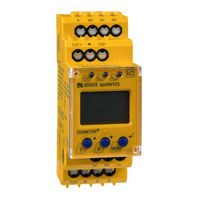
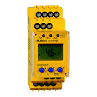
Insulation monitoring device for unearthed IT AC-, AC/DC and DC systems
Brand: Bender
|
Category: Measuring Instruments
|
Size: 2 MB
Table of Contents
Advertisement

Bender ISOMETER isoRW425 Manual (72 pages)
Insulation monitoring device for unearthed IT AC-, AC/DC and DC systems (IT systems) for railway applications up to 3(N)AC, AC/DC 440 V
Brand: Bender
|
Category: Measuring Instruments
|
Size: 1 MB
Table of Contents

Bender ISOMETER isoRW425 Manual (50 pages)
Insulation monitoring device for unearthed IT AC-, AC/DC and DC systems (IT systems) for railway applications up to 3(N)AC, AC/DC 440 V
Brand: Bender
|
Category: Power distribution unit
|
Size: 2 MB
Table of Contents
Advertisement

Bender ISOMETER isoRW425 Manual (48 pages)
Insulation monitoring device
Brand: Bender
|
Category: Measuring Instruments
|
Size: 4 MB
Table of Contents
Bender ISOMETER isoRW425 Manual (60 pages)
Insulation monitoring device for unearthed IT AC-, AC/DC and DC systems for railway applications up to AC/DC 400 V
Brand: Bender
|
Category: Measuring Instruments
|
Size: 1 MB
Table of Contents
Bender ISOMETER isoRW425 Quick Start Manual (13 pages)
Insulation monitoring device for unearthed IT AC-, AC/DC and DC systems (IT systems) for railway applications up to 3(N)AC, AC/DC 440 V
Brand: Bender
|
Category: Measuring Instruments
|
Size: 0 MB
Table of Contents

Bender ISOMETER isoRW425 Quick Start Manual (12 pages)
Brand: Bender
|
Category: Measuring Instruments
|
Size: 0 MB