Bender ISOMETER isoRW425 Manual
Insulation monitoring device for unearthed it ac-, ac/dc and dc systems (it systems) for railway applications up to 3(n)ac, ac/dc 440 v
Hide thumbs
Also See for ISOMETER isoRW425:
- Manual (76 pages) ,
- Quick start manual (13 pages) ,
- Quick start manual (12 pages)
Table of Contents

Related Manuals for Bender ISOMETER isoRW425


Summary of Contents for Bender ISOMETER isoRW425
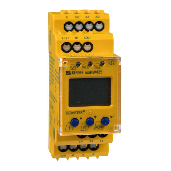
- Page 1 ISOMETER® isoRW425 Insulation monitoring device for unearthed IT AC-, AC/DC and DC systems (IT systems) for railway applications up to 3(N)AC, AC/DC 440 V Software version: D0418 V2.xx isoRW425_D00052_05_M_XXEN / 04.2021 Manual EN...
- Page 2 Service and support for Bender products First-level support Technical support Carl-Benz-Strasse 8 • 35305 Grünberg • Germany Telephone: +49 6401 807-760 0700BenderHelp * Fax: +49 6401 807-629 E-mail: support@bender.de Available on 365 days from 7.00 a.m. to 8.00 p.m. (MEZ/UTC +1) * Landline German Telekom: Mon-Fri from 9.00 a.m.
-
Page 3: Table Of Contents
Indication of important instructions and information ........5 1.2.1 Signs and symbols ......................5 Training courses and seminars.................5 Delivery conditions .......................6 Inspection, transport and storage ................6 Warranty and liability....................6 Disposal of Bender devices ..................6 Safety ..........................7 Intended use ........................7 Function ....................8 Device features ......................8 Functional description ....................9 2.2.1 Monitoring of the insulation resistance (R mode) ......... - Page 4 4.4.3 Fault memory configuration .................. 24 4.4.4 Interface configuration .................... 24 Menu „t“ ......................... 24 4.5.1 Time configuration ....................24 Menu „SEt“ ........................25 4.6.1 Function configuration .................... 25 Measuring value display and history memory ..........26 Data access using the BMS protocol ........... 27 Data access using the Modbus RTU protocol ......
-
Page 5: General Instructions
Training courses and seminars www.bender.de > Know-how-> Seminars. Delivery conditions The conditions of sale and delivery set out by Bender apply. These can be obtained from Bender in printed or electronic format. The following applies to software products: “Software clause in respect of the licensing of standard software as part of de-... -
Page 6: Inspection, Transport And Storage
• Non-observance of technical data. • Repairs carried out incorrectly. • Use of accessories and spare parts not recommended by Bender. • Catastrophes caused by external influences and force majeure. • Mounting and installation with device combinations not recommended by the manufac- turer. -
Page 7: Safety
ISOMETER® isoRW425 Safety If the device is used outside the Federal Republic of Germany, the applicable local standards and regulations must be complied with. In Europe, the European standard EN 50110 applies. ! Risk of electrocution due to electric shock! anger Touching live parts of the system carries the risk of: •... -
Page 8: Intended Use
• Measured value indication via multi-functional LCD • Fault memory can be activated • RS-485 (galvanically isolated) including the following protocols: – BMS interface (Bender measuring device interface) for data exchange with other Bender components – Modbus RTU – IsoData (for continuous data output) •... -
Page 9: Functional Description
ISOMETER® isoRW425 Functional description The ISOMETER® measures the insulation resistance R and the system leakage capacitance C between the system to be monitored (L1/+, L2/-) and earth (PE). Z mode (selectable in the „SEt“ menu) calculates the insulation impedance Z from R and C with a system frequency parameter... -
Page 10: Monitoring Of The Insulation Resistance (R Mode)
Function 2.3.1 Monitoring of the insulation resistance (R mode) The two parameters that monitor the insulation resistance, „R1“ and „R2“, can be found in the menu „AL“ (see table on page 22). The value R1 can only be set higher than the value R2. Each time the mode is switched from R mode to Z mode, parameters „R1“... -
Page 11: Self Test/Error Codes
ISOMETER® isoRW425 2.3.4 Self test/error codes The integrated self-test function checks the function of the insulation monitoring device and the connection monitoring checks the connections to the system to be monitored. The alarm relays are not switched during the self test. This can be changed using the parameter „test“ in the alarm assignment (see Chapter 5.4 Menu „out“). -
Page 12: Malfunction
„E.xx“ appears on the display as an identifier for the error type xx and the LEDs „ON“/“AL1“/„AL2“ will flash. If the error occurs again after restarting the device or after a reset to factory settings, then contact Bender Service. isoRW425_D00052_05_M_XXEN / 04.2021... -
Page 13: Assignment Of The Alarm Relays K1/K2
ISOMETER® isoRW425 2.3.6 Assignment of the alarm relays K1/K2 The messages „device error“, „insulation fault“, „insulation impedance fault“,„undervoltage/over- voltage fault“, „device test“ or „device start with alarm“ can be assigned to the alarm relays via the „out“ menu. An insulation fault is indicated by the messages „+R1“, „-R1“, „+R2“ and „-R2“. Messages „+R1“... -
Page 14: Password Protection (On, Off)
Function Response delay t The response delay t is set uniformly for all messages in the menu „t“ using the parameter „ton“. This delay time can be used for interference suppression in the case of short measuring times. An alarm will only be signalled when a threshold value of the respective measuring value is violated for the period of t without interruption. -
Page 15: Fault Memory
The ISOMETER® uses the serial hardware interface RS-485 with the following protocols: • BMS The BMS protocol is an essential component of the Bender measuring device interface (BMS bus protocol). ASCII characters are used for the data transfer. • Modbus RTU... -
Page 16: Installation, Connection And Commissioning
Installation, connection and commissioning Installation, connection and commissioning Application in railway vehicles/DIN EN 45545-2:2016 If the horizontal or vertical distance to adjacent components which do not meet the requirements in table 2 of DIN EN 45545-2 is less than 20 mm or less than 200 mm respectively, they are to be regarded as grouped. -
Page 17: Wiring Diagram
ISOMETER® isoRW425 Wiring diagram L1/+ L2/- L1/+ Test / Reset MENU COM465IP RS-485 For details about the conductor cross sections required for wiring, refer to the technical data on page Legend Terminal Connections Connection to the supply voltage U via fuse (line protection): A1, A2 If supplied from an IT system, both lines have to be protected by a fuse.* Connect each terminal separately to PE:... -
Page 18: Commissioning
Installation, connection and commissioning Commissioning 1. Check that the ISOMETER® is properly connected to the system to be monitored. 2. Connect the supply voltage U to the ISOMETER®. The device carries out a calibration, a self test and adjusts itself to the IT system to be monitored. -
Page 19: Device Operation
ISOMETER® isoRW425 Device operation The menu structure is illustrated schematically on the following pages. After pressing the „MENU“ button for > 1.5 s, the first menu item „AL“ appears. Use (Enter) buttons for navigation and settings. Up and down button: •... -
Page 20: Display Elements
Device operation Display elements Device front/display Function green - On yellow - Alarm yellow - Alarm Assignment according to table on page 23 Up button Test button (press > 1.5 s) Down button Reset button (press > 1.5 s) ENTER MENU MENU button (press >... -
Page 21: Menu Structure
ISOMETER® isoRW425 Menu structure Measurement display Menu selection Parameter selection > < 1.5 s > > . . . 1.5 s 1.5 s < t > 5 Min. < > 1.5 s Z [kΩ] R [kΩ] C [µF] U L1 L2 [V ] <... -
Page 22: Menu „Al
Device operation Menu „AL“ 4.3.1 Response value setting Only after activating Z mode in the „SEt“ menu, the response values „Z1“ as well as „Z2“ appear on the display and are activated. Simultaneously, the response values „R1“ and „R2“ are set to position off, but can then be set to on again. -
Page 23: Relay Alarm Assignment „R1" And „R2" And Led Assignment
ISOMETER® isoRW425 4.4.2 Relay alarm assignment „r1“ and „r2“ and LED assignment In the alarm assignment, each alarm is assigned to the corresponding relay with the setting „on“. The LED indication is directly assigned to the alarms and is not related to the relays. If the device can assign an asymmetrical insulation fault to the corresponding conductor (L1/+ or L2/-), it will only signal the respective alarm. -
Page 24: Fault Memory Configuration
Device operation 4.4.3 Fault memory configuration Display Description Memory function for alarm messages (fault memory) FAC = Factory setting; Cs = Customer settings 4.4.4 Interface configuration Display Setting value Description Range Adr = 0 deactivates BMS as well as Modbus 0/3…90 Bus-Adr. -
Page 25: Menu „Set
Z 50.0/60.0 50,0 and select associated system frequency Test the system connection during device test S.Ct Device test during device start Restore factory settings For Bender Service only FAC = Factory setting; Cs = Customer settings isoRW425_D00052_05_M_XXEN / 04.2021... -
Page 26: Measuring Value Display And History Memory
Device operation Measuring value display and history memory In R mode only R and in Z mode only Z is permanently shown on the display (standard display). All other measuring value displays switch to the standard display after a maximum of 5 min. The fault location will only be stored in the history memory („HiS“) in R mode. -
Page 27: Data Access Using The Bms Protocol
ISOMETER® isoRW425 Data access using the BMS protocol The BMS protocol is an essential component of the Bender measuring device interface (BMS bus protocol). ASCII characters are used for the data transfer. BMS channel no. Operation value Alarm Pre-alarm R1... -
Page 28: Data Access Using The Modbus Rtu Protocol
Data access using the Modbus RTU protocol Data access using the Modbus RTU protocol Requests to the ISOMETER® can be made using the function code 0x03 (read multiple registers) or the command 0x10 (write multiple registers). The ISOMETER® generates a function-related answer and sends it back. -
Page 29: Write Modbus Register (Parameter Setting)
ISOMETER® isoRW425 Write Modbus register (parameter setting) Registers in the device can be modified with the function code 0x10 (Write Multiple Registers). Parameter registers are available from address 3000. The content of the register is listed in the table on page 6.2.1 Command of the Master to the ISOMETER®... -
Page 30: Exception Code
Data access using the Modbus RTU protocol Exception code If a request cannot be answered for whatever reason, the ISOMETER® will send a so-called exception code with which possible faults can be narrowed down. Exception code Description 0x01 Impermissible function 0x02 Impermissible data access 0x03... -
Page 31: Modbus Register Assignment Of The Isometer
ISOMETER® isoRW425 Modbus register assignment of the ISOMETER® The information in the registers is: the measuring value without alarm; the measuring value with alarm 1; the measuring value with alarm 2; or only the device fault, depending on the device condition. - Page 32 Modbus register assignment of the ISOMETER® Register Permissions Description Format Unit Value range Number of Modbus measured value channels with UINT 16 0…9 active alarm Activation of prealarm value impedance measure- 3000 UINT 16 [2]/[3] * ment „Z1“ 3001 Pre-alarm value impedance measurement „Z1“ UINT 16 kΩ...
- Page 33 ISOMETER® isoRW425 Register Permissions Description Format Unit Value range 3018 Start-up delay „t“ during device start UINT 16 0…10 3019 Response delay „ton“ for relays „K1“ and „K2“ UINT 16 0…99 3020 Delay on release „toff“ for relays „K1“ and „K2“ UINT 16 0…99 0 = OFF...
- Page 34 Modbus register assignment of the ISOMETER® Register Permissions Description Format Unit Value range UNIT 16 (ASCII) - 9800 to 9809 Device name refer to chapter 7.1.1 Software ID 9820 Software ID number UINT 16 number Software 9821 Software version number UINT 16 version 9822...
-
Page 35: Device-Specific Data Types Of The Isometer
ISOMETER® isoRW425 Device-specific data types of the ISOMETER® 7.1.1 Device name The data format of the device name is specified below. Word 0x01 0x02 0x03 ------------------- 0x08 0x09 0x00 10 Words in total Each Word contains two ASCII characters 7.1.2 Measuring values Each measuring value is available as a channel and consists of 8 bytes (4 registers). -
Page 36: At&T = Alarm Type And Test Type (Internal/External)
Modbus register assignment of the ISOMETER® 7.1.2.2 AT&T = Alarm type and test type (internal/external) 6 5 4 3 Meaning No alarm Prewarning Device error Reserved Warning Alarm Reserved … … … Reserved Reserved No test Internal test External test The alarm type is coded by bits 0 to 2. -
Page 37: R&U = Range And Unit
ISOMETER® isoRW425 7.1.2.3 R&U = Range and unit Meaning Invalid (init) No unit Ω Baud °C °F Second Minute Hour Month Actual value The actual value is lower The actual value is higher Invalid value • The units of bits 0 to 4 are coded. •... -
Page 38: Alarm Assignment Of The Relays
Modbus register assignment of the ISOMETER® 7.1.3 Alarm assignment of the relays Several alarms can be assigned to each relay. For the assignment of each relay, a 16-bit-register is used with the bits described below. The following table applies to relay 1 and relay 2, in which „x“ stands for the relay number. -
Page 39: Channel Descriptions
ISOMETER® isoRW425 Channel descriptions Measuring value description/ Value Alarm message Note Operating message 1 (0x01) Insulation fault 71 (0x47) Insulation fault Insulation resistance R in Ω 76 (0x4C) Voltage Measured value in V 77 (0x4D) Undervoltage 78 (0x4E) Overvoltage 82 (0x52) Capacitance Measured value in F 86 (0x56) - Page 40 Modbus register assignment of the ISOMETER® To convert parameter data, data type descriptions are required. Text representation is not necessary in this case. Value Description of parameters Parameter/measured value invalid. 1023 (0x3FF) The menu item of this parameter is not displayed. 1022 (0x3FE) No measured value/no message 1021 (0x3FD)
-
Page 41: Isodata Data String
ISOMETER® isoRW425 IsoData data string In IsoData mode, the ISOMETER® continuosly sends the whole data string with a cycle time of ap- proximately 1 s. Communication with the ISOMETER® within this mode is not possible and no ad- ditional sender may be connected via the RS-485 bus cable. IsoData is activated in the menu „out“, menu item „Adr“... -
Page 42: Technical Data
Technical data Technical data Tabular presentation ( )* = factory setting Insulation coordination acc. to IEC 60664-1/IEC 60664-3 Definitions: Measuring circuit (IC1) ..............................L1/+, L2/- Supply circuit (IC2) ................................A1, A2 Output circuit (IC3) ................................ 11, 14, 24 Control circuit (IC4) ..............................E, KE, T/R, A, B Rated voltage ...................................... - Page 43 ISOMETER® isoRW425 Measuring circuit Measuring voltage U ..................................±12 V Measuring current I at R = 0 Ω .............................. ≤ 110 μA Internal resistance R ................................. ≥ 115 kΩ Permissible system leakage capacitance C (R mode) ........................≤ 300 μF Permissible system leakage capacitance C (Z mode) .........................
- Page 44 Technical data Interface Interface/protocol ..........................RS-485/BMS, Modbus RTU, isoData Baud rate ....................BMS (9.6 kbit/s), Modbus RTU (selectable), isoData (115.2 kbit/s) Cable length (9.6 kbit/s) ................................≤ 1 200 m Cable: shield connected to PE on one side ..................recommended: CAT6/CAT7 min. AWG23* * alternative: twisted pairs, shield connected to PE on one side ..................
-
Page 45: Standards, Approvals And Certifications
ISOMETER® isoRW425 Push-wire terminals: Nominal current ....................................≤ 10 A Conductor sizes .................................... AWG 24-14 Stripping length ....................................10 mm Rigid .......................................0.2…2.5 mm flexible without ferrules................................0.75…2.5 mm flexible with ferrules with/without plastic sleeve .........................0.25…2.5 mm Multi-conductor flexible with TWIN ferrules with plastic sleeve ..................................0.5…1.5 mm Opening force ...................................... -
Page 46: Revision History
Technical data Document revision history Valid from Date Document version software State/Changes version 04.2021 D0418 V2.08 Editorial revision Added: chapter 2.3.10: Note on stopped measuring function Added: chapter 3: Safety instruction acc. to DIN EN 45545-2:2016 Changed: chapter 3.3: Wiring diagram chapter 4.2: Menu overview represen- tation Corrected:... - Page 47 ISOMETER® isoRW425 isoRW425_D00052_05_M_XXEN / 04.2021...
- Page 48 isoRW425_D00052_05_M_XXEN / 04.2021...
- Page 49 ISOMETER® isoRW425 isoRW425_D00052_05_M_XXEN / 04.2021...
- Page 50 Nachdruck und Vervielfältigung Reprinting and duplicating nur mit Genehmigung des Herausgebers. only with permission of the publisher. Bender GmbH & Co. KG Bender GmbH & Co. KG Postfach 1161 • 35301 Grünberg • Deutschland PO Box 1161 • 35301 Grünberg • Germany Londorfer Str.
Need help?
Do you have a question about the ISOMETER isoRW425 and is the answer not in the manual?
Questions and answers