Bender ISOMETER isoRW425 Quick Start Manual
Insulation monitoring device for unearthed it ac-, ac/dc and dc systems (it systems) for railway applications up to 3(n)ac, ac/dc 440 v
Hide thumbs
Also See for ISOMETER isoRW425:
- Manual (76 pages) ,
- Quick start manual (12 pages) ,
- Manual (60 pages)
Table of Contents
Advertisement
Quick Links
Kurzanleitung DE
Quick-start guide EN
ISOMETER® isoRW425
Isolationsüberwachungsgerät für ungeerdete AC, AC/DC-
und DC-Stromversorgungen (IT-Systeme) für Bahn-Applikationen
bis 3(N)AC, AC/DC 440 V
Insulation monitoring device for unearthed IT AC-, AC/DC
and DC systems (IT systems) for railway applications
up to 3(N)AC, AC/DC 440 V
isoRW425_D00052_06_Q_DEEN / 11.2023
Advertisement
Table of Contents

Related Manuals for Bender ISOMETER isoRW425


Summary of Contents for Bender ISOMETER isoRW425
- Page 1 Kurzanleitung DE Quick-start guide EN ISOMETER® isoRW425 Isolationsüberwachungsgerät für ungeerdete AC, AC/DC- und DC-Stromversorgungen (IT-Systeme) für Bahn-Applikationen bis 3(N)AC, AC/DC 440 V Insulation monitoring device for unearthed IT AC-, AC/DC and DC systems (IT systems) for railway applications up to 3(N)AC, AC/DC 440 V isoRW425_D00052_06_Q_DEEN / 11.2023...
- Page 2 Make sure that the relevant personnel has read the Handbuch und die Sicherheitshinweise gelesen und manual and understood all instructions relating to verstanden hat. safety. https://www.bender.de/service-support/downloadbereich/ https://www.bender.de/en/service-support/download-area/ Dieses Dokument enthält nur einen Auszug der This document contains only an overview of the wichtigsten technischen Daten. Die gesamten ta- most important technical data.
-
Page 3: Montage
ISOMETER® isoRW425 Zwischen L1/+ und L2/– muss, für die korrekte To ensure that the ISOMETER® functions correctly, Funktion des ISOMETER®s, ein Netzinnenwider- an internal resistance of ≤ 1 kΩ must exist bet- stand ≤ 1 kΩ über die Quelle (z. B. Transformator) ween L1/+ and L2/–... -
Page 4: Wiring Diagram
ISOMETER® isoRW425 Anschlussbild Wiring diagram L1/+ L2/- L1/+ L2/- E KE Test / Reset MENU COM465IP RS-485 Klemme / Anschlüsse Connections Terminal Anschluss an die Versorgungsspannung U über Schmelzsicherung: Connection to the supply voltage U via a fuse: Bei Versorgung aus IT-System beide Leitungen absichern. A1, A2 If supplied from an IT system, both lines have to be protected by a fuse. -
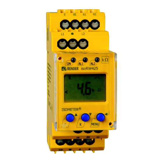
Page 5: Control Panel
ISOMETER® isoRW425 Bedienfeld Control panel Funktion Gerätefront/Device front Element Function grün - On green - On gelb - Vorwarnung yellow - Pre-warning gelb - Alarm yellow - Alarm Aufwärts-Taste Up button Test-Taste (> 1,5 s drücken) Test button (press > 1.5 s) Bei gedrückter Test-Taste werden die By pressing and holding the test button, Display-Elemente angezeigt. -
Page 6: Menü-Übersicht
ISOMETER® isoRW425 Menü-Übersicht Menu overview Messwertanzeige Menüauswahl Parametereingabe Measurement display Menu selection Parameter selection > < 1.5 s > > 1.5 s 1.5 s . . . < t > 5 Min. < > 1.5 s R [k ] C [µF] U L1 L2 [V] U L1 [V] <... - Page 7 ISOMETER® isoRW425 Inbetriebnahme Commissioning 1. Korrekten Anschluss des ISOMETER®s an das zu 1. Check that the ISOMETER® is properly connected to überwachende Netz prüfen. the system to be monitored. 2. Versorgungsspannung U für ISOMETER® zuschal- 2. Connect the supply voltage U to the ISOMETER®.
-
Page 8: Error Codes
If the error continues to exist after checking the device Fehler weiterhin auftritt, liegt ein Fehler im Gerät vor. connections, there is an error inside the device. Gerätefehler - Kontakt zum Bender-Service aufnehmen. E.xx Device error - Contact Bender Service... -
Page 9: Technische Daten
ISOMETER® isoRW425 Technische Daten Technical data ()* = Werkseinstellung ()* = Factory settings Isolationskoordination nach IEC 60664-1/IEC 60664-3 Insulation coordination acc. to IEC 60664-1/IEC 60664-3 Bemessungsspannung ..............440 V Rated voltage ................. 440 V Überspannungskategorie ..............III Overvoltage category ................III Versorgungsspannung Supply voltage Versorgungsspannung U ...... - Page 10 ISOMETER® isoRW425 Anschluss Connection Anschlussart ..........Schraub- oder Federklemme Connection type .........screw-type or push-wire terminal Schraubklemmen: Screw-type terminals: Nennstrom ................... ≤ 10 A Nominal current ................≤ 10 A Anzugsmoment ..........0,5…0,6 Nm (5…7 lb-in) Tightening torque .........0.5…0.6 Nm (5…7 lb-in) Leitergrößen .................AWG 24-12 Conductor sizes ..............AWG 24-12 Abisolierlänge ................8 mm...
-
Page 11: Eu-Konformitätserklärung
ISOMETER® isoRW425 EU-Konformitätserklärung EU Declaration of Conformity Bender GmbH & Co. KG erklärt, dass das unter die Funk- Bender GmbH & Co. KG declares that the device covered richtlinie fallende Gerät der Richtlinie 2014/53/EU ent- by the Radio Directive complies with Directive 2014/53/ spricht. - Page 12 Alle Rechte vorbehalten. 35305 Grünberg Nachdruck und Vervielfältigung nur mit Germany Genehmigung des Herausgebers. © Bender GmbH & Co. KG, Germany Subject to change! The specified Tel.: +49 6401 807-0 All rights reserved. standards take into account the edition info@bender.de...
Need help?
Do you have a question about the ISOMETER isoRW425 and is the answer not in the manual?
Questions and answers