NXP Semiconductors QorIQ LS1028A Reference Manual
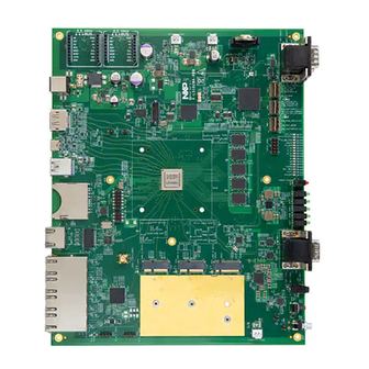
Reference design board
Hide thumbs
Also See for QorIQ LS1028A:
- Getting started manual (18 pages) ,
- Reference manual (112 pages) ,
- Reference manual (115 pages)

Subscribe to Our Youtube Channel
Related Manuals for NXP Semiconductors QorIQ LS1028A


Summary of Contents for NXP Semiconductors QorIQ LS1028A
- Page 1 NXP Semiconductors Document identifier: LS1028ARDBRM Reference Manual Rev. 3, 07 February 2022 QorIQ LS1028A Reference Design Board Reference Manual Supports LS1028ARDB Revision C...
-
Page 2: Table Of Contents
3.1 Register Conventions......................58 3.2 Resets............................. 59 3.3 Identification Registers......................59 3.4 Identification (ID)........................59 3.5 Board Version (VER)....................... 60 3.6 Qixis Version (QVER)......................61 QorIQ LS1028A Reference Design Board Reference Manual, Rev. 3, 07 February 2022 Reference Manual 2 / 116... - Page 3 3.57 Interrupt Status 1 (IRQSTAT1).................... 102 3.58 Interrupt Status 2 (IRQSTAT2).................... 102 3.59 Interrupt Drive 5 (IRQDRV5)....................103 3.60 Programmable Interrupt Controller..................104 3.61 PIC Edge (PIC_EDGE)......................104 QorIQ LS1028A Reference Design Board Reference Manual, Rev. 3, 07 February 2022 Reference Manual 3 / 116...
- Page 4 3.68 Core Management Address (CMSA)...................111 3.69 Core Management Data (CMSD)..................111 Appendix A How to use LS1027A device on LS1028ARDB......113 Appendix B Revision History................114 QorIQ LS1028A Reference Design Board Reference Manual, Rev. 3, 07 February 2022 Reference Manual 4 / 116...
-
Page 5: Chapter 1 Ls1028Ardb Overview
Chapter 1 LS1028ARDB overview The QorIQ LS1028A reference design board (LS1028ARDB) provides a comprehensive platform that enables design and evaluation of the LS1028A processor, which is a dual-core Arm Cortex-v8 A72 processor with frequency up to 1.3 GHz. The board is lead-free and RoHS-compliant. - Page 6 Serial peripheral interface Spread spectrum Spread spectrum clocking TCXO Temperature compensated crystal (Xtal) oscillator UART Universal asynchronous receiver/transmitter Table continues on the next page... QorIQ LS1028A Reference Design Board Reference Manual, Rev. 3, 07 February 2022 Reference Manual 6 / 116...
-
Page 7: Related Documentation
QorIQ LS1028A Chip Errata Lists the details of all known silicon errata for the LS1028A Contact FAE / sales representative QorIQ LS1028A Reference... -
Page 8: Block Diagram
IEEE1588 Connector & 1PPS SMA RGMII Audio Codec SGTL5000 & SAI4 TX LINE OUT Audio LINEOUT (for Speakers) Figure 1. LS1028ARDB block diagram QorIQ LS1028A Reference Design Board Reference Manual, Rev. 3, 07 February 2022 Reference Manual 8 / 116... -
Page 9: Board Features
— x1, x4, and x8 I/Os — SDR/DDR modes up to 52 MHz clock speed — HS200/HS400 modes Table continues on the next page... QorIQ LS1028A Reference Design Board Reference Manual, Rev. 3, 07 February 2022 Reference Manual 9 / 116... - Page 10 • Supports display resolution of up to 4Kp60 • Supports link transfer rates of up to HBR2 (5.4 Gbit/s) Table continues on the next page... QorIQ LS1028A Reference Design Board Reference Manual, Rev. 3, 07 February 2022 Reference Manual 10 / 116...
- Page 11 • Socket and heat sink are included System logic CPLD • Manages the following: — System reset sequencing Table continues on the next page... QorIQ LS1028A Reference Design Board Reference Manual, Rev. 3, 07 February 2022 Reference Manual 11 / 116...
- Page 12 LS1028ARDB feature Specification Description — SoC POR configuration at reset • Implements registers for system control and monitoring • General fault monitoring and logging QorIQ LS1028A Reference Design Board Reference Manual, Rev. 3, 07 February 2022 Reference Manual 12 / 116...
-
Page 13: Chapter 2 Ls1028Ardb Functional Description
• System controller 2.1 Processor ® ® The LS1028ARDB board is based on the QorIQ LS1028A processor having two Arm Cortex - A72 processor cores. The LS1028ARDB board supports as many features of the LS1028A as possible. NOTE For more details about the LS1028A processor, see QorIQ LS1028A Reference Manual . - Page 14 MIKROBUS CONNECTORS LEDs MISC PARTS (BUFFERS & TRANSLATORS USB_HVDD LS1028 USB_HVDD 3.3V @ .45 A LPF x2 Figure 2. Power supplies - Part 1 QorIQ LS1028A Reference Design Board Reference Manual, Rev. 3, 07 February 2022 Reference Manual 14 / 116...
- Page 15 The figure below shows the filters used. 5.1OHm 0.33OHm 2.2uF 2.2uF 10uF 47uF 4.7uF 0.22uF 2.2uF =NFM18PC225B1A3 2.2uF =GRM155R60J225KE95 Figure 4. Passive low pass filters QorIQ LS1028A Reference Design Board Reference Manual, Rev. 3, 07 February 2022 Reference Manual 15 / 116...
-
Page 16: Primary Power Supply
LS1028A). MC34716EP 1.2 V at 4 A DDR4 DRAM memories Semiconductors LS1028A DRAM controller core and I/O Table continues on the next page... QorIQ LS1028A Reference Design Board Reference Manual, Rev. 3, 07 February 2022 Reference Manual 16 / 116... - Page 17 Jumper-enabled 1V8 also powers PROG_MTR and PROG_SFP. FPF1321UCX EVDD eSDHC IO Power. 3.3 V Semiconductor 1.8 V Table continues on the next page... QorIQ LS1028A Reference Design Board Reference Manual, Rev. 3, 07 February 2022 Reference Manual 17 / 116...
-
Page 18: Power Supply Sequence
On the availability of 12 V supply to the power regulators, the orderly enable of all power supplies are sequenced using powergood of the regulators, as shown in the following figure. QorIQ LS1028A Reference Design Board Reference Manual, Rev. 3, 07 February 2022 Reference Manual... - Page 19 Figure 5. Power up voltage sequence NOTE The LS1028ARDB follows the power supply sequencing requirements as detailed in QorIQ LS1028A Data Sheet . QorIQ LS1028A Reference Design Board Reference Manual, Rev. 3, 07 February 2022 Reference Manual 19 / 116...
-
Page 20: Current And Power Measurement
The 5P49V5907B520NDGI is a programmable clock generator that generates most of the clocks. Clock configurations are stored in its one-time programmable (OTP) memory. The configuration in volatile memory can be changed through the I2C1_CH1 QorIQ LS1028A Reference Design Board Reference Manual, Rev. 3, 07 February 2022 Reference Manual... - Page 21 1588 port LVCMOS • Operating voltage: 1.8 V 27 MHz crystal Frequency: 27 MHz Display port DP_REFCLK_P Table continues on the next page... QorIQ LS1028A Reference Design Board Reference Manual, Rev. 3, 07 February 2022 Reference Manual 21 / 116...
-
Page 22: Ddr Interface
VCC_GVDD_S (1.2 V), VTT (0.6 V) and VREFCA (0.6 V). The memory interface including all the necessary termination and I/O power are routed, as shown in the following figure. QorIQ LS1028A Reference Design Board Reference Manual, Rev. 3, 07 February 2022 Reference Manual... -
Page 23: Usb Interface
(DFP) or upstream facing port (UFP). Based on the configuration detected on the Type C port, the USB2 PHY can operate either in host or device mode. The following figure shows the architecture of the USB 3.0 interface. QorIQ LS1028A Reference Design Board Reference Manual, Rev. 3, 07 February 2022 Reference Manual... - Page 24 Both, USB1 and USB2 connectors have an LED nearby, USB1_5V and USB2_5V, respectively, which are active when the +5 V USB power supply is enabled to the connectors. QorIQ LS1028A Reference Design Board Reference Manual, Rev. 3, 07 February 2022 Reference Manual...
-
Page 25: Displayport
Figure 9. SerDes architecture The LS1028A SerDes module support several protocols, which are assigned to dedicated functions on the LS1028ARDB, as shown in the table below. QorIQ LS1028A Reference Design Board Reference Manual, Rev. 3, 07 February 2022 Reference Manual 25 / 116... -
Page 26: Ethernet Controller Interface
The onboard Ethernet PHY, Qualcomm AR8033 PHY (U23) connects to the ENETC of the LS1028A processor using SGMII protocol over SerDes lane A. QorIQ LS1028A Reference Design Board Reference Manual, Rev. 3, 07 February 2022 Reference Manual 26 / 116... -
Page 27: Qsgmii Ethernet
The onboard Ethernet PHY, NXP F104S8A PHY (U24), connects to the TSN switch of the LS1028 processor using QSGMII protocol over SerDes lane B. QorIQ LS1028A Reference Design Board Reference Manual, Rev. 3, 07 February 2022 Reference Manual 27 / 116... -
Page 28: Ieee 1588 Interface
The LS1028A processor provides support for the IEEE 1588 precision time protocol (PTP), which works in tandem with ENETC to timestamp the incoming packets. A 12-pin header (J11) is provided on the board to allow support for 1588 protocol. The SMA QorIQ LS1028A Reference Design Board Reference Manual, Rev. 3, 07 February 2022 Reference Manual... -
Page 29: Synchronous Audio Interface (Sai)
The LS1028ARDB board supports audio through NXP SGTL5000-32QFN audio codec (U93). The board supports one audio LINEOUT (J34) for headphone and stereo speakers. The figure below shows the LS1028ARDB audio interface architecture. QorIQ LS1028A Reference Design Board Reference Manual, Rev. 3, 07 February 2022 Reference Manual... -
Page 30: Connectors
M.2 connector select Signal name Mount resistor/capacitor Values Type E PEXM2_2_REFCLK_P R214 0 Ω PEXM2_2_REFCLK_N R213 0 Ω Table continues on the next page... QorIQ LS1028A Reference Design Board Reference Manual, Rev. 3, 07 February 2022 Reference Manual 30 / 116... -
Page 31: Adapters
It is recommended to use UART1 as a debug port. The LTC2804-1 transceiver can support 1 Mbit/s data rate on each of the serial ports. The figure below shows the LS1028ARDB DUART connections. QorIQ LS1028A Reference Design Board Reference Manual, Rev. 3, 07 February 2022 Reference Manual 31 / 116... -
Page 32: Can Interface
The TJA1052T/3 transceivers can support data rate of up to 5 Mbit/s in CAN with Flexible Data-Rate (CAN FD) phase. The figure below shows the CAN architecture. QorIQ LS1028A Reference Design Board Reference Manual, Rev. 3, 07 February 2022 Reference Manual... -
Page 33: I2C Interface
(1.8 V to 3.3 V and 3.3 V to 1.8 V) for CPLD and external I2C devices. The figure below shows the I2C bus architecture. QorIQ LS1028A Reference Design Board Reference Manual, Rev. 3, 07 February 2022 Reference Manual... - Page 34 All channels on I2C1 are translated to 3V3 except channel 1, which operates at 1V8 (OVDD) power supply. The I2C devices available on the I2C1 bus are shown in the figure below. QorIQ LS1028A Reference Design Board Reference Manual, Rev. 3, 07 February 2022 Reference Manual...
- Page 35 I2C1_CH0 0x50 Atmel AT24C512C-XHD UEFI/ boot memory Provides I2C booting B: 64 KB EEPROM option. Write protectable. Table continues on the next page... QorIQ LS1028A Reference Design Board Reference Manual, Rev. 3, 07 February 2022 Reference Manual 35 / 116...
- Page 36 BLE / BEE / NFC Provides I2C connectivity defined by the to mikroBUS click plugged-in mikro modules on connectors click module J31 and J32. QorIQ LS1028A Reference Design Board Reference Manual, Rev. 3, 07 February 2022 Reference Manual 36 / 116...
-
Page 37: Xspi Interface
• 512 MB, PBGA24 x1/x4 SPI NAND ITES:F flash memory • Supports 166 MHz SDR speed • Powers up in x1 mode Table continues on the next page... QorIQ LS1028A Reference Design Board Reference Manual, Rev. 3, 07 February 2022 Reference Manual 37 / 116... -
Page 38: Jtag Port
The JTAG port provides access to the processor using a standard 10-pin Arm Cortex JTAG connector for debugging purposes. The following figure shows the LS1028ARDB JTAG architecture. QorIQ LS1028A Reference Design Board Reference Manual, Rev. 3, 07 February 2022 Reference Manual... -
Page 39: Esdhc Interface
(FPF1321UCX) changes the 3.3 V supply to 1.8 V for the controller depending upon the value of SDHC_VSEL signal. The following table describes EVDD switch output voltage depending upon the SD card speed and SDHC_VSEL value. QorIQ LS1028A Reference Design Board Reference Manual, Rev. 3, 07 February 2022 Reference Manual... -
Page 40: Mikrobus Click Modules
Figure 19. mikroBUS architecture The following table describes some of the mikroBUS click modules (boards) that can be used on the mikroBUS sockets. QorIQ LS1028A Reference Design Board Reference Manual, Rev. 3, 07 February 2022 Reference Manual 40 / 116... - Page 41 1: PWM (FTM1_CH1) routed to mikroBUS2 module. Also, the click modules on mikroBUS1 or mikroBUS2 can be accessed directly through I2C1 channel 6 or channel 7, respectively. QorIQ LS1028A Reference Design Board Reference Manual, Rev. 3, 07 February 2022 Reference Manual 41 / 116...
-
Page 42: Gpios
0x77 0x0B 0x0B Program primary I2C bus multiplexer (PCA9848PWJ) to get access to I2C1_CH3 (I2C sub-channel for SA56004ED) Table continues on the next page... QorIQ LS1028A Reference Design Board Reference Manual, Rev. 3, 07 February 2022 Reference Manual 42 / 116... -
Page 43: Dip Switches
XSPI_A device mapping devices/peripherals. CFG_XSPI_MAP Table 26. XSPI_A device mapping Bit value XSPI_A_CS0 XSPI_A_CS1 Description sNOR sNAND Normal NOR (default setting) sNAND sNOR Normal NAND QorIQ LS1028A Reference Design Board Reference Manual, Rev. 3, 07 February 2022 Reference Manual 43 / 116... - Page 44 LS1018AE 1 core, GPU enabled, security enabled 0x870B2110 LS1018AN 1 core, GPU enabled, security disabled 0x870B2410 LS1017AE 1 core, GPU disabled, security enabled QorIQ LS1028A Reference Design Board Reference Manual, Rev. 3, 07 February 2022 Reference Manual 44 / 116...
- Page 45 SW5[5] Boot Box mode SW_BOOTBOX_B • 0: Enable boot-box mode • 1: Normal operating mode (default setting) Table continues on the next page... QorIQ LS1028A Reference Design Board Reference Manual, Rev. 3, 07 February 2022 Reference Manual 45 / 116...
-
Page 46: Leds
Yellow ASLEEP The processor has not exited Sleep mode, which generally indicates: • Improper RCW source selection Table continues on the next page... QorIQ LS1028A Reference Design Board Reference Manual, Rev. 3, 07 February 2022 Reference Manual 46 / 116... - Page 47 Indicates that the LS1028A processor is in socket The following table lists all the LEDs available on the front-panel of the LS1028ARDB board chassis. QorIQ LS1028A Reference Design Board Reference Manual, Rev. 3, 07 February 2022 Reference Manual 47 / 116...
-
Page 48: Multi-Status Leds
User-defined (if register CTL[1] (LED) = 1) Not applicable M[3:0] reflect contents of (see Table the LED register Not applicable Not applicable Heartbeat: Clock monitor QorIQ LS1028A Reference Design Board Reference Manual, Rev. 3, 07 February 2022 Reference Manual 48 / 116... -
Page 49: System Controller
• Remapping of system boot devices • Handling of board control and status registers The following figures show the system controller architectural details. QorIQ LS1028A Reference Design Board Reference Manual, Rev. 3, 07 February 2022 Reference Manual 49 / 116... - Page 50 BOM rev PCB_REV[2:0] 000 = “Rev A” 001 = “Rev B” Selectively DNP resistors to encode PCB rev Figure 20. System controller architecture QorIQ LS1028A Reference Design Board Reference Manual, Rev. 3, 07 February 2022 Reference Manual 50 / 116...
-
Page 51: System Configuration
BRDCFG and DUTCFG registers. BRDCFG registers are always active, and software may change them to result in immediate changes to the system configuration. DUTCFG registers are used to control processor configuration pins that are only sampled QorIQ LS1028A Reference Design Board Reference Manual, Rev. 3, 07 February 2022 Reference Manual... - Page 52 Controls how XSPI_A chip-select 0 is connected to devices/peripherals. CFG_MEM_WP SW3[4] CTL[3] Allows/prevents write to SYSTEM ID, UEFI flash, and DDR4 SPD. Table continues on the next page... QorIQ LS1028A Reference Design Board Reference Manual, Rev. 3, 07 February 2022 Reference Manual 52 / 116...
-
Page 53: Reset Sequencing
The LS1028A processor asserts ASLEEP and HRESET_B in response. ASLEEP is monitored with an LED, otherwise the signals are ignored. Table continues on the next page... QorIQ LS1028A Reference Design Board Reference Manual, Rev. 3, 07 February 2022 Reference Manual 53 / 116... - Page 54 RCW source location. When RCW loading is complete, the LS1028A processor de-asserts HRESET_B and ASLEEP. Table continues on the next page... QorIQ LS1028A Reference Design Board Reference Manual, Rev. 3, 07 February 2022 Reference Manual 54 / 116...
- Page 55 The CPLD has finished reset management. The reset sequencer watches for reset switch events and will restart at reset sequencer step 1 if any are detected. QorIQ LS1028A Reference Design Board Reference Manual, Rev. 3, 07 February 2022 Reference Manual 55 / 116...
-
Page 56: Chapter 3 Qixis Programming Model
Reconfiguration Control (RCFG) 0001x00xb 010h USB Control (USB_STAT) 00000001b 01Dh USB Control (USB_CTL) 00100000b 01Eh Watchdog (WATCH) 00011111b 01Fh Table continues on the next page... QorIQ LS1028A Reference Design Board Reference Manual, Rev. 3, 07 February 2022 Reference Manual 56 / 116... - Page 57 DUT Configuration 1 (DUTCFG1) 01111111b 061h DUT Configuration 2 (DUTCFG2) 11111xx1b 062h DUT Configuration 11 (DUTCFG11) x1111111b 06Bh Table continues on the next page... QorIQ LS1028A Reference Design Board Reference Manual, Rev. 3, 07 February 2022 Reference Manual 57 / 116...
-
Page 58: Register Conventions
Read as 1. Write ones to unused bits. others Read as 0. Write zeros to unused bits. Future definitions of reserved bits will maintain backward compatibility with the above rules. QorIQ LS1028A Reference Design Board Reference Manual, Rev. 3, 07 February 2022 Reference Manual 58 / 116... -
Page 59: Resets
The ID register contains a unique classification number. This ID number is used by system software to identify board types. The ID number remains same for all board revisions. QorIQ LS1028A Reference Design Board Reference Manual, Rev. 3, 07 February 2022 Reference Manual... -
Page 60: Board Version (Ver)
Field Function Board architecture version: ARCH 1= V1 2= V2 (etc.) PCB board version: 1= Rev A (or pre-release) 2= Rev B (etc.) QorIQ LS1028A Reference Design Board Reference Manual, Rev. 3, 07 February 2022 Reference Manual 60 / 116... -
Page 61: Qixis Version (Qver)
Register Offset MODEL 003h Function The MODEL register contains information about the software programming model version and PCB Bill Of Materials (BOM) information. QorIQ LS1028A Reference Design Board Reference Manual, Rev. 3, 07 February 2022 Reference Manual 61 / 116... -
Page 62: Minor Revision (Minor)
The MINOR (or MINTAG) register can be used to obtain CPLD build information from software. The register returns a subset of the Qixis QTAG facility but more than the limited MINOR facility on other RDBs. QorIQ LS1028A Reference Design Board Reference Manual, Rev. 3, 07 February 2022 Reference Manual... - Page 63 0x30-7F reserved reserved Diagram Bits MINOR NONE Fields Field Function Read: Data to read from MINOR/MINTAG. MINOR Write: Address of data to read. QorIQ LS1028A Reference Design Board Reference Manual, Rev. 3, 07 February 2022 Reference Manual 63 / 116...
-
Page 64: Control And Status Registers
0= FAIL LED is not asserted due to software (it might still be on due to hardware failures). 1= FAIL LED is forced on. Generally, this indicates a software-diagnosed error. QorIQ LS1028A Reference Design Board Reference Manual, Rev. 3, 07 February 2022 Reference Manual... -
Page 65: Auxiliary (Aux)
00000000 Fields Field Function User-defined value. 3.12 System Status (STAT_SYS) Address Register Offset STAT_SYS 009h Function The STAT_SYS register reports general system status. QorIQ LS1028A Reference Design Board Reference Manual, Rev. 3, 07 February 2022 Reference Manual 65 / 116... -
Page 66: Alarm (Alarm)
The ALARM register detects and reports any alarms raised in the QIXIS system. Write 1 to an ALARM register bit to prevent Qixis from recognizing that alarm condition. By default, all alarms are handled. QorIQ LS1028A Reference Design Board Reference Manual, Rev. 3, 07 February 2022 Reference Manual... -
Page 67: Presence Detect 1 (Stat_Pres1)
3.14 Presence Detect 1 (STAT_PRES1) Address Register Offset STAT_PRES1 00Bh Function The STAT_PRES1 register detects the presence and type of processor installed. QorIQ LS1028A Reference Design Board Reference Manual, Rev. 3, 07 February 2022 Reference Manual 67 / 116... -
Page 68: Presence Detect 2 (Stat_Pres2)
3.15 Presence Detect 2 (STAT_PRES2) Address Register Offset STAT_PRES2 00Ch Function The STAT_PRES2 register detects the installation of cards in various PCI Express or SGMII slots. QorIQ LS1028A Reference Design Board Reference Manual, Rev. 3, 07 February 2022 Reference Manual 68 / 116... -
Page 69: Led Control (Led)
The LED register can be used to directly control the monitoring LEDs (M3-M0) for software debugging or other purposes. Direct control of the LEDs is possible only when CTL[LED] is set to 1; otherwise they are used to display general system activity. QorIQ LS1028A Reference Design Board Reference Manual, Rev. 3, 07 February 2022 Reference Manual... -
Page 70: Reconfiguration Registers
The RCFG register is used to control the reconfiguration sequencer. Diagram Bits LIVE WDEN CRST SW_BOOT... RRST Fields Field Function Reserved. Table continues on the next page... QorIQ LS1028A Reference Design Board Reference Manual, Rev. 3, 07 February 2022 Reference Manual 70 / 116... -
Page 71: Usb Control (Usb_Stat)
1= On the 0-to-1 transition, the reconfiguration process begins. 3.19 USB Control (USB_STAT) Address Register Offset USB_STAT 01Dh Function The USB_STAT register reports USB 2 port status. QorIQ LS1028A Reference Design Board Reference Manual, Rev. 3, 07 February 2022 Reference Manual 71 / 116... -
Page 72: Usb Control (Usb_Ctl)
1= USB2 ID is high (UFP mode). 3.20 USB Control (USB_CTL) Address Register Offset USB_CTL 01Eh Function The USB_CTL register manages USB features, principally USB fault control and/or status. QorIQ LS1028A Reference Design Board Reference Manual, Rev. 3, 07 February 2022 Reference Manual 72 / 116... -
Page 73: Watchdog (Watch)
Note that the watchdog timer is not dependent upon a reconfiguration sequence being active. While it is typically enabled along with RCFG[GO] as part of a reconfiguration sequence; in fact, it is independent and can be enabled for any reason. QorIQ LS1028A Reference Design Board Reference Manual, Rev. 3, 07 February 2022 Reference Manual... -
Page 74: Power Control/Status Registers
PMBus/I2C interface). 3.23 Power Control 2 (PWR_CTL2) Address Register Offset PWR_CTL2 021h Function The PWR_CTL2 register is used to control system power-on/power-off events. QorIQ LS1028A Reference Design Board Reference Manual, Rev. 3, 07 February 2022 Reference Manual 74 / 116... -
Page 75: Power Status 0 (Pwr_Mstat)
Main Power Supply Control Status: ATXON 0= Power supply is set to off. 1= Power supply is set to on. Table continues on the next page... QorIQ LS1028A Reference Design Board Reference Manual, Rev. 3, 07 February 2022 Reference Manual 75 / 116... -
Page 76: Power Status 1 (Pwr_Stat1)
The PWR_STAT1 registers is used to monitor the status of individual power supplies. If a bit is set to '1', the respective power supply is operating correctly. QorIQ LS1028A Reference Design Board Reference Manual, Rev. 3, 07 February 2022 Reference Manual... -
Page 77: Clock Control Registers
1= Power supply is operating. 3.26 Clock Control Registers The clock control registers control programmable clock synthesizers used to supply clocks to the processor and associated peripherals. QorIQ LS1028A Reference Design Board Reference Manual, Rev. 3, 07 February 2022 Reference Manual 77 / 116... -
Page 78: Clock Speed 1 (Clk_Spd1)
The CLK_ID register is used to identify the arrangement of the clock control registers. Software should check CLK_ID register before attempting to interpret/control the clock control registers. QorIQ LS1028A Reference Design Board Reference Manual, Rev. 3, 07 February 2022 Reference Manual... -
Page 79: Reset Control Registers
The RST_CTL register is used configure or trigger reset actions. Diagram Bits REQMD DDRLK ARST CRST SW_RST_MODE Fields Field Function Reserved. Table continues on the next page... QorIQ LS1028A Reference Design Board Reference Manual, Rev. 3, 07 February 2022 Reference Manual 79 / 116... -
Page 80: Reset Status (Rst_Stat)
1= Upon transition from 0 to 1, restart the reset sequence. 3.31 Reset Status (RST_STAT) Address Register Offset RST_STAT 041h Function The RST_STAT register reports the current status of various reset-related signals. QorIQ LS1028A Reference Design Board Reference Manual, Rev. 3, 07 February 2022 Reference Manual 80 / 116... -
Page 81: Reset Event Trace (Rst_Reason)
3.32 Reset Event Trace (RST_REASON) Address Register Offset RST_REASON 042h Function The RST_REASON register is used to report the cause of the most-recent reset cycle. QorIQ LS1028A Reference Design Board Reference Manual, Rev. 3, 07 February 2022 Reference Manual 81 / 116... -
Page 82: Reset Force 1 (Rst_Force1)
1, the reset signal to grouped devices will be asserted. Resetting a resource while in used by the bootloader or OS will typically cause crashes, etc. Use carefully. QorIQ LS1028A Reference Design Board Reference Manual, Rev. 3, 07 February 2022 Reference Manual... -
Page 83: Reset Force 2 (Rst_Force2)
Reset DDR DIMM. 1= Assert RST_MEM_B 3.34 Reset Force 2 (RST_FORCE2) Address Register Offset RST_FORCE2 044h Function Assert selected reset sources. See RST_FORCE1 for details. QorIQ LS1028A Reference Design Board Reference Manual, Rev. 3, 07 February 2022 Reference Manual 83 / 116... -
Page 84: Reset Force 3 (Rst_Force3)
NOTE: This bit only asserts the signal to the DUT; it is not intended to be used as a general system reset. 3.35 Reset Force 3 (RST_FORCE3) Address Register Offset RST_FORCE3 045h Function Assert selected reset sources. See RST_FORCE1 for details. QorIQ LS1028A Reference Design Board Reference Manual, Rev. 3, 07 February 2022 Reference Manual 84 / 116... -
Page 85: Reset Mask 1 (Rst_Mask1)
Note that RST_MASK bits are cleared on AUX reset, and so are usually only cleared by software. This is very different from the RST_FORCE registers. QorIQ LS1028A Reference Design Board Reference Manual, Rev. 3, 07 February 2022 Reference Manual 85 / 116... -
Page 86: Reset Mask 2 (Rst_Mask2)
Reset DDR DIMMs. 1= Mask RST_MEM_B 3.37 Reset Mask 2 (RST_MASK2) Address Register Offset RST_MASK2 04Ch Function Mask selected reset sources. See RST_FORCE1 for details. QorIQ LS1028A Reference Design Board Reference Manual, Rev. 3, 07 February 2022 Reference Manual 86 / 116... -
Page 87: Reset Mask 2 (Rst_Mask3)
1= Mask DUT_PORESET_B. PORST 3.38 Reset Mask 2 (RST_MASK3) Address Register Offset RST_MASK3 04Dh Function Mask selected reset sources. See RST_FORCE1 for details. QorIQ LS1028A Reference Design Board Reference Manual, Rev. 3, 07 February 2022 Reference Manual 87 / 116... -
Page 88: Board Configuration Registers
3.40 Board Configuration 0 (BRDCFG0) Address Register Offset BRDCFG0 050h Function The BRDCFG0 register is commonly used to select IFC and QSPI boot devices. QorIQ LS1028A Reference Design Board Reference Manual, Rev. 3, 07 February 2022 Reference Manual 88 / 116... -
Page 89: Board Configuration 1 (Brdcfg1)
011= EMU sNAND 100= sNOR Reserved. 3.41 Board Configuration 1 (BRDCFG1) Address Register Offset BRDCFG1 051h Function The BRDCFG1 register shows/controls SYSCLK and DDRCLK speeds. QorIQ LS1028A Reference Design Board Reference Manual, Rev. 3, 07 February 2022 Reference Manual 89 / 116... -
Page 90: Board Configuration 2 (Brdcfg2)
The BRDCFG2 register reporst SerDes clock speeds for SerDes blocks 1 and 2. Diagram Bits SD1CK1 SD1CK2 RRST 0000 Fields Field Function SerDes1 Clock #1 Rate: Table continues on the next page... QorIQ LS1028A Reference Design Board Reference Manual, Rev. 3, 07 February 2022 Reference Manual 90 / 116... -
Page 91: Board Configuration 3 (Brdcfg3)
Controls routing of UART2 (nets CFG_MUX_UART2*): UART2 00= Routed to RS232 transceiver and DB9 connector P1A (default). 01= reserved. Table continues on the next page... QorIQ LS1028A Reference Design Board Reference Manual, Rev. 3, 07 February 2022 Reference Manual 91 / 116... -
Page 92: Board Configuration 4 (Brdcfg4)
PX1WD 0= Board operates normally. 1= Board wireless shutdown requested. PCI Express M.2 Wireless disable (net CFG_PEX2_WDIS_B): Table continues on the next page... QorIQ LS1028A Reference Design Board Reference Manual, Rev. 3, 07 February 2022 Reference Manual 92 / 116... -
Page 93: Board Configuration 5 (Brdcfg5)
For V8 or later, the default is 0. Reserved. 3.45 Board Configuration 5 (BRDCFG5) Address Register Offset BRDCFG5 055h Function The BRDCFG5 register manages uBUS1 connections and status. QorIQ LS1028A Reference Design Board Reference Manual, Rev. 3, 07 February 2022 Reference Manual 93 / 116... -
Page 94: Board Configuration 6 (Brdcfg6)
11= RST pin treated as output, asserted high. 3.46 Board Configuration 6 (BRDCFG6) Address Register Offset BRDCFG6 056h Function The BRDCFG6 register manages uBUS2 connections and status. QorIQ LS1028A Reference Design Board Reference Manual, Rev. 3, 07 February 2022 Reference Manual 94 / 116... -
Page 95: Dut Configuration Registers
- they are driven only during the reset configuration sampling interval (PORESET_B assertion), and remain tri-stated thereafter. Refer to the device hardware specification for hardware pin-sampled timing parameters. QorIQ LS1028A Reference Design Board Reference Manual, Rev. 3, 07 February 2022 Reference Manual... -
Page 96: Dut Configuration 0 (Dutcfg0)
Note that the RCW_SRC settings are mapped to equivalent 9-bit values when an LS1043A interposer is connected. 3.49 DUT Configuration 1 (DUTCFG1) Address Register Offset DUTCFG1 061h QorIQ LS1028A Reference Design Board Reference Manual, Rev. 3, 07 February 2022 Reference Manual 96 / 116... -
Page 97: Dut Configuration 2 (Dutcfg2)
The DUTCFG2 register manages device selection (SVR) and internal-only device test features. Diagram Bits SVR01 TEST RRST 11111 SW_SVR Fields Field Function Reserved. Table continues on the next page... QorIQ LS1028A Reference Design Board Reference Manual, Rev. 3, 07 February 2022 Reference Manual 97 / 116... -
Page 98: Dut Configuration 11 (Dutcfg11)
3.52 GPIO Registers The GPIO registers provide an 8-bit general-purpose GPIO port. For the LS1028A RDB, the following connections are provided: LS1028A GPIO3\[4:2\] => QorIQ LS1028A Reference Design Board Reference Manual, Rev. 3, 07 February 2022 Reference Manual 98 / 116... -
Page 99: Gpio I/O (Gpio_Io)
IO port values (if corresponding DIR.n is 1): 0= output pin driven to level 0. 1= output pin driven to level 1. Same as IO4. Same as IO4. Reserved. QorIQ LS1028A Reference Design Board Reference Manual, Rev. 3, 07 February 2022 Reference Manual 99 / 116... -
Page 100: Gpio Direction (Gpio_Dir)
0= output pin driven to level 0. 1= output pin driven to level 1. Same as DIR4. DIR3 Same as DIR4. DIR3 Reserved. QorIQ LS1028A Reference Design Board Reference Manual, Rev. 3, 07 February 2022 Reference Manual 100 / 116... -
Page 101: Irq Status Registers
Reserved. Interrupt input IRQ_RTC_B: 0: Interrupt is asserted. Reserved. Interrupt input IRQ_UBUS2_B: UBUS2 0: Interrupt is asserted. Table continues on the next page... QorIQ LS1028A Reference Design Board Reference Manual, Rev. 3, 07 February 2022 Reference Manual 101 / 116... -
Page 102: Interrupt Status 1 (Irqstat1)
NONE 11111 Fields Field Function Reserved. 1: TMP_DETECT_B signal is high. TATMPDET Reserved. 3.58 Interrupt Status 2 (IRQSTAT2) Address Register Offset IRQSTAT2 092h QorIQ LS1028A Reference Design Board Reference Manual, Rev. 3, 07 February 2022 Reference Manual 102 / 116... -
Page 103: Interrupt Drive 5 (Irqdrv5)
Allows control of the TMP_DETECT_B pin. TMP_CTL 0X= Undriven (Z). 10= Drive TMP_DETECT_B low. 11= Drive TMP_DETECT_B high. Table continues on the next page... QorIQ LS1028A Reference Design Board Reference Manual, Rev. 3, 07 February 2022 Reference Manual 103 / 116... -
Page 104: Programmable Interrupt Controller
Register Offset PIC_EDGE 0A0h Function PIC_EDGE selects between edge-triggered and level-sensitive modes for each individual interrupt inputs, defaulting to level sensitive by default. QorIQ LS1028A Reference Design Board Reference Manual, Rev. 3, 07 February 2022 Reference Manual 104 / 116... -
Page 105: Pic Polarity (Pic_Pol)
Function PIC_POL sets the polarity of interrupt inputs, whether level-sensitive (0) or edge-sensitive (1) on an individual level. See PIC_EDGE for mode selection. QorIQ LS1028A Reference Design Board Reference Manual, Rev. 3, 07 February 2022 Reference Manual 105 / 116... -
Page 106: Pic Mask (Pic_Mask)
PIC_MASK controls whether interrupts are handled or ignored. By default, less-used interrupts are masked and must be specifically enabled, while ethernet-related interrupts are unmasked. QorIQ LS1028A Reference Design Board Reference Manual, Rev. 3, 07 February 2022 Reference Manual 106 / 116... -
Page 107: Pic Mask (Pic_Pend)
(by writing a 1) to clear the status. Bits, once set, remain active until cleared, even if the input has changed or the interrupt signal is removed. QorIQ LS1028A Reference Design Board Reference Manual, Rev. 3, 07 February 2022 Reference Manual... -
Page 108: Pic Status (Pic_Stat)
0= Idle. 1= Level- or edge-triggered interrupt was detected. 3.65 PIC Status (PIC_STAT) Address Register Offset PIC_STAT 0A6h Function PIC_STAT shows general PIC information. QorIQ LS1028A Reference Design Board Reference Manual, Rev. 3, 07 February 2022 Reference Manual 108 / 116... -
Page 109: Pic Control (Pic_Ctl)
Since there is no interrupt vector into the LS1028, this register can be used by software if desired. 3.66 PIC Control (PIC_CTL) Address Register Offset PIC_CTL 0A7h Function PIC_CTL controls optional features of the PIC. QorIQ LS1028A Reference Design Board Reference Manual, Rev. 3, 07 February 2022 Reference Manual 109 / 116... -
Page 110: Core Management Space Registers
= Qixis_Get_Reg( CMS_D ); for (i = 1; i <= nr; i++) { Qixis_Set_Reg( CMS_A, i ); printf("SW%1d = %02X\\ n", i, Qixis_Get_Reg( CMS_D )); QorIQ LS1028A Reference Design Board Reference Manual, Rev. 3, 07 February 2022 Reference Manual 110 / 116... -
Page 111: Core Management Address (Cmsa)
3.69 Core Management Data (CMSD) Address Register Offset CMSD 0D9h Function CMSD contains the value of a CMS register selected by CMSA. See CMSA for details. QorIQ LS1028A Reference Design Board Reference Manual, Rev. 3, 07 February 2022 Reference Manual 111 / 116... - Page 112 NXP Semiconductors Qixis Programming Model Diagram Bits DATA ARST 00000000 Fields Field Function Read/write internal CMS registers selected with CMSA. DATA QorIQ LS1028A Reference Design Board Reference Manual, Rev. 3, 07 February 2022 Reference Manual 112 / 116...
-
Page 113: Appendix A How To Use Ls1027A Device On Ls1028Ardb
2. Replace LS1028A silicon (U12) with LS1027A part. 3. Change SW3.2 DIP switch value to ‘0’ (OFF) position. This changes TESTSEL_B to low. QorIQ LS1028A Reference Design Board Reference Manual, Rev. 3, 07 February 2022 Reference Manual 113 / 116... -
Page 114: Appendix B Revision History
How to use LS1027A device Added the Appendix. on LS1028ARDB DIP switches Updated Table Adapters Added a note in this section. Rev. 0 02/2019 Initial public release. QorIQ LS1028A Reference Design Board Reference Manual, Rev. 3, 07 February 2022 Reference Manual 114 / 116... - Page 115 NXP sells products pursuant to standard terms and conditions of sale, which can be found at the following address: nxp.com/SalesTermsandConditions. Right to make changes - NXP Semiconductors reserves the right to make changes to information published in this document, including without limitation specifications and product descriptions, at any time and without notice.
- Page 116 © NXP B.V. 2019-2022. All rights reserved. For more information, please visit: http://www.nxp.com For sales office addresses, please send an email to: salesaddresses@nxp.com Date of release: 07 February 2022 Document identifier: LS1028ARDBRM...
Need help?
Do you have a question about the QorIQ LS1028A and is the answer not in the manual?
Questions and answers