Table of Contents
Advertisement
Quick Links
KW45B41Z-EVKUM
KW45B41Z-EVK Board User Manual
Rev. 2 — 13 February 2023
Document information
Information
Keywords
Abstract
Content
KW45B41Z-EVKUM, KW45B41Z-EVK, KW45B41Z, Bluetooth LE 5.3, CAN FD, LIN
The KW45B41Z-EVK board is a highly configurable, low-power, and cost-effective, evaluation and
development platform for NXP KW45B41Z MCU, which is a low-power, highly secure, single-chip
wireless MCU supporting Arm Cortex-M33 core
User manual
Advertisement
Table of Contents

Related Manuals for NXP Semiconductors KW45B41Z-EVK


Summary of Contents for NXP Semiconductors KW45B41Z-EVK
- Page 1 KW45B41Z-EVKUM, KW45B41Z-EVK, KW45B41Z, Bluetooth LE 5.3, CAN FD, LIN Abstract The KW45B41Z-EVK board is a highly configurable, low-power, and cost-effective, evaluation and development platform for NXP KW45B41Z MCU, which is a low-power, highly secure, single-chip wireless MCU supporting Arm Cortex-M33 core...
-
Page 2: Kw45B41Z-Evk Overview
NXP. It can be used with a wide range of development tools, including NXP MCUXpresso IDE and IAR Embedded Workbench. The board is lead-free and RoHS-compliant. For debugging the KW45B41Z MCU, the KW45B41Z-EVK board uses an onboard debug probe, known as MCU-Link OB (OB stands for "onboard"), which is based on another MCU, LPC55S69. For simplicity, MCU- Link OB is referred to as "MCU-Link debug probe"... - Page 3 KW45B41Z-EVKUM NXP Semiconductors KW45B41Z-EVK Board User Manual Table 1. Acronyms and abbreviations ...continued Term Description Controller area network Do not populate Flexible data-rate GFSK Gaussian frequency shift keying Ground GPIO General-purpose input/output General-purpose output Human interface device Human–machine interaction High-speed Inter-integrated circuit...
-
Page 4: Related Documentation
KW45B41Z-EVK board. Some of the documents listed below may be available only under a non-disclosure agreement (NDA). To request access to these documents, contact your local field applications engineer (FAE) or sales representative. -
Page 5: Block Diagram
I/O headers Arduino Uno R3 I/O headers Figure 1. KW45B41Z-EVK block diagram 1.6 Board features Table 3 describes the features of the KW45B41Z-EVK board. Table 3. KW45B41Z-EVK features Board feature Target MCU feature used Description MCU (target MCU) KW45B41Z MCU with Arm Cortex-M33 core running at a... - Page 6 KW45B41Z-EVKUM NXP Semiconductors KW45B41Z-EVK Board User Manual Table 3. KW45B41Z-EVK features ...continued Board feature Target MCU feature used Description LPUART/LIN Two LPUART modules (LPUART0 • LPUART0: and LPUART1) – Connects to a 1x4 pin LIN header through a LIN transceiver for an external LIN connection –...
-
Page 7: Board Pictures
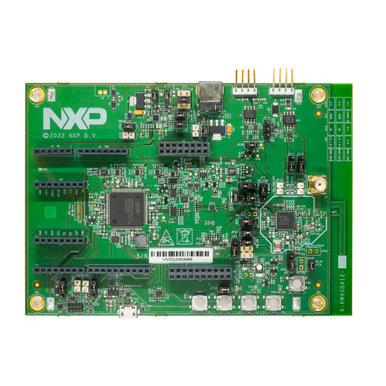
• 10-pin Arm JTAG/SWD connector for connecting an external debug probe 1.7 Board pictures Figure 2 shows the top-side view of the KW45B41Z-EVK board, with connectors, push buttons, and LEDs highlighted. KW45B41Z-EVKUM All information provided in this document is subject to legal disclaimers. - Page 8 LED2 (SWD) (target MCU boot) (wake-up) (USB) Figure 2. KW45B41Z-EVK connectors, push buttons, and LEDs (top-side view) Figure 3 shows the jumpers of the KW45B41Z-EVK board. KW45B41Z-EVKUM All information provided in this document is subject to legal disclaimers. © 2023 NXP B.V. All rights reserved.
- Page 9 JP26 JP25 Figure 3. KW45B41Z-EVK jumpers Figure 4 shows the bottom-side view of the KW45B41Z-EVK board, with battery holder BT2 highlighted. KW45B41Z-EVKUM All information provided in this document is subject to legal disclaimers. © 2023 NXP B.V. All rights reserved. User manual Rev.
-
Page 10: Connectors
KW45B41Z-EVKUM NXP Semiconductors KW45B41Z-EVK Board User Manual (battery holder) Figure 4. KW45B41Z-EVK bottom-side view 1.8 Connectors Table 4 describes the KW45B41Z-EVK connectors. The connectors are shown in Figure 2 Figure Table 4. KW45B41Z-EVK connectors Part identifier Connector type Description Reference section BT1 (DNP) -
Page 11: Jumpers
Section 3.5 external debug probe or external debug target J15 (DNP) 2x5 pin header MCU-Link SWD connector 1.9 Jumpers Table 5 describes the KW45B41Z-EVK jumpers. The jumpers are shown in Figure Table 5. KW45B41Z-EVK jumpers Part identifier Jumper type Description Reference section... - Page 12 KW45B41Z-EVKUM NXP Semiconductors KW45B41Z-EVK Board User Manual Table 5. KW45B41Z-EVK jumpers ...continued Part identifier Jumper type Description Reference section JP42 1x2 pin header Target MCU debugging enable jumper: • Open: Target MCU debugging is disabled. Note: To use VBAT supply (coincell power)
- Page 13 KW45B41Z-EVKUM NXP Semiconductors KW45B41Z-EVK Board User Manual Table 5. KW45B41Z-EVK jumpers ...continued Part identifier Jumper type Description Reference section • 2-3 shorted: VDD_IO_ABC supply is produced from MCU_VDD_REG supply 1x3 pin header VDD_ANA supply power source selection jumper: • 1-2 shorted (default setting): VDD_ANA supply is produced from VDD_REG supply •...
- Page 14 KW45B41Z-EVKUM NXP Semiconductors KW45B41Z-EVK Board User Manual Table 5. KW45B41Z-EVK jumpers ...continued Part identifier Jumper type Description Reference section JP13 (DNP) 1x2 pin header VOUT_SYS / VDD_SYS supply enable jumpers. JP13 and JP40 are not populated on the board. JP40 (DNP)
- Page 15 KW45B41Z-EVKUM NXP Semiconductors KW45B41Z-EVK Board User Manual Table 5. KW45B41Z-EVK jumpers ...continued Part identifier Jumper type Description Reference section • Open (default setting): MCU-Link is connected to the target MCU through a USB- to-UART bridge • Shorted: The USB-to-UART bridge between...
-
Page 16: Push Buttons
This setting of JP22 can be used when connecting an external debug probe for debugging the target MCU. 1.10 Push buttons Table 6 describes the KW45B41Z-EVK push buttons. The push buttons are shown in Figure Table 6. KW45B41Z-EVK push buttons Part identifier PCB label... -
Page 17: Leds
Figure 5. Push button circuit diagram 1.11 LEDs Table 7 describes the KW45B41Z-EVK light-emitting diodes (LEDs) that correspond to the target MCU. The board also has some MCU-Link specific LEDs, which are described in Section 3.9. The LEDs are shown in... -
Page 18: Kw45B41Z-Evk Functional Description
Figure 6. LED circuit diagrams 2 KW45B41Z-EVK functional description This section describes the features and functions of the KW45B41Z-EVK board. You can use the functionality described in this section as a reference while designing your own target board. Note: For more details on the KW45B41Z MCU, see KW45 Product Family Data Sheet and KW45B41Z Reference Manual. -
Page 19: Power Supplies
LIN transceiver, mikroBUS socket, Arduino socket, Ranger 4 UWB socket, push buttons, and LEDs. Many power supplies in the KW45B41Z-EVK board are produced through jumpers, which can be used to configure their respective power supplies. This configuration includes enabling/disabling a power supply and changing input power source for a power supply. - Page 20 KW45B41Z-EVKUM NXP Semiconductors KW45B41Z-EVK Board User Manual Secondary Coin cell VBAT option holder VBAT LiIon / Ext Battery P3V3_BATT P3V3_BATT RB160M-30 RB160M-30 HDR 1X2 10uF SMTU2450N-LF S8421-45R VBAT power P12V P12V_VBAT P12V P5V_CAN Ex t e r n a l 1 2 V...
- Page 21 JP14 to limit current peaks. For more information, see E-4: VDD_RF supply does not have a series resistor. Table 8 describes the KW45B41Z-EVK power supplies. KW45B41Z-EVKUM All information provided in this document is subject to legal disclaimers. © 2023 NXP B.V. All rights reserved.
- Page 22 KW45B41Z-EVKUM NXP Semiconductors KW45B41Z-EVK Board User Manual Table 8. KW45B41Z-EVK power supplies Power source Manufacturing part Power supply rail Description number Coincell battery holder S8421-45R VBAT (3.3 V) • One of the three power supplies used to BT2 (primary option) produce P3V3 supply Note: BT1 and BT2 •...
- Page 23 KW45B41Z-EVKUM NXP Semiconductors KW45B41Z-EVK Board User Manual Table 8. KW45B41Z-EVK power supplies ...continued Power source Manufacturing part Power supply rail Description number maximum current: 250 mA) SW2_OUT: PMIC_ Produces P1V8_EXT supply SW2 (default voltage: 1.8 V, maximum current: 500 mA) LDO2_OUT: PMIC_...
- Page 24 KW45B41Z-EVKUM NXP Semiconductors KW45B41Z-EVK Board User Manual Table 8. KW45B41Z-EVK power supplies ...continued Power source Manufacturing part Power supply rail Description number From PMIC_SW2 output P1V8_EXT (1.8 V) • Produces VDD_PA_2G4 supply through jumper of PMIC through jumper JP11 (DNP) • One of the three power supplies used to produce V_SEC supply •...
-
Page 25: Current Measurement
MCU-Link debug probe. For more details, see Section 3.8. 2.1.1 Current measurement The KW45B41Z-EVK board supports the following two methods for measuring current on some of the board power supplies: • Using onboard MCU-Link current measurement circuit. This method is explained in Section 3.8. -
Page 26: Power Modes
Bypass mode, PMIC mode, or Smart Power Switch mode) involves reconfiguring some of the board jumpers. Changing power mode also involves cutting traces at the bottom side of the PCB. Table 10 explains how to switch the KW45B41Z-EVK board from one power mode to another power mode by changing jumper settings. Table 10. Power mode switching... -
Page 27: Dc-Dc Inductor
1. Set CNTRL[CORELDO_EN] = 0 2. Set CNTRL[DCDC_EN] = 0 2.1.3 DC-DC inductor The KW45B41Z-EVK board uses a 1 μH DC-DC inductor L1 (TDK MLZ2012A1R0WTD25). The inductor is enabled when the board is configured in DC-DC Buck mode. Figure 10 shows the DC-DC inductor circuit diagram of the KW45B41Z-EVK board. -
Page 28: Clocks
16 MHz MCU-Link (LPC55S69) In the KW45B41Z-EVK board, the target MCU requires the following two clocks: • 32 MHz clock (with ±30 ppm accuracy): Provides clock inputs to the Arm Cortex-M33 core and 2.4 GHz radio • 32.768 kHz clock: Provides an accurate low-power timebase and acts as real-time clock (RTC) and low-power... -
Page 29: Can Interface
The target MCU has a FlexCAN module (CAN0), which supports controller area network (CAN) and CAN flexible data rate (FD). The KW45B41Z-EVK board allows communication with CAN0 module through a high- speed CAN transceiver, which drives CAN signals between CAN0 module and a physical two-wire CAN bus that terminates at a 1x4 pin header. -
Page 30: Lpuart/Lin Interface
• J10 provides pins to interface with a CAN bus • Pin 3 of J10 can be used to power up other KW45B41Z-EVK boards • Pin 3 of the J10 can also be used as an input to power up the KW45B41Z-EVK board 2.4 LPUART/LIN interface The target MCU (KW45B41Z) has two Low-Power Universal Asynchronous Receiver/Transmitter (LPUART) modules, LPUART0 and LPUART1, with local interconnect network (LIN) support. - Page 31 By default, MCU-Link is connected to the LPUART1 controller. It can be connected to the LPUART0 controller by changing the setting of each of the jumpers JP16 and JP17 from 1-2 shorted to 2-3 shorted. Table 13 provides more details on LPUART/LIN connections in the KW45B41Z-EVK board. Table 13. KW45B41Z-EVK LPUART/LIN connections LPUART...
- Page 32 • Pin 2 of J11 can be used to power up other KW45B41Z-EVK boards • Pin 2 of J11 can also be used as an input to power up the KW45B41Z-EVK board • The LIN_RX signal is a bidirectional signal whose direction can be controlled by changing the jumper JP19 settings as follows: –...
-
Page 33: Lpspi Interface
The target MCU has two Low-Power Serial Peripheral Interface (LPSPI) modules: LPSPI0 and LPSPI1. Each LPSPI module can act as a SPI master or slave, and supports four peripheral chip selects (PCSes): PCS0, PCS1, PCS2, and PCS3. The KW45B41Z-EVK board only supports LPSPI1 module, with all its PCSes. Figure 18 shows the KW45B41Z-EVK LPSPI diagram. -
Page 34: Lpi2C Interface
• The SPI signals can be shared with other peripherals through Arduino socket DH connector J2 2.6 LPI2C interface The target MCU (KW45B41Z) has two Low-Power Inter-Integrated Circuit (LPI2C) modules: LPI2C0 and LPI2C1. The KW45B41Z-EVK board only supports LPI2C1 module. Figure 20 shows the KW45B41Z-EVK LPI2C diagram. -
Page 35: Rf Interface
(LE) version 5.3 radio. The radio transceiver operates in the 2.4 GHz frequency band, supporting Gaussian frequency shift keying (GFSK) modulations for Bluetooth LE 5.3. The KW45B41Z-EVK board provides a small-footprint, low-cost RF interface for users to begin application development. -
Page 36: Accelerometer
2.5 V (which is also the maximum voltage supported on the pin) 2.8 Accelerometer The KW45B41Z-EVK board has a 3-axis, 12-bit, compact digital accelerometer U12 (NXP FXLS8964AF) with ±2g / ±4g / ±8g / ±16g acceleration support and selectable I2C. It is designed to be used for applications requiring ultra-low-power wake-up on motion. -
Page 37: Mikrobus Socket
A mikroBUS socket is a pair of 1x8 position receptacles (connectors) with a proprietary pin configuration. It allows maximum hardware expandability with smallest number of pins. The KW45B41Z-EVK board has a mikroBUS socket with two 1x8 position receptacles, J12 and J13. Figure 24 shows the pinouts of the mikroBUS socket connectors. -
Page 38: Arduino Socket
2.10 Arduino socket The KW45B41Z-EVK board has an Arduino socket with four connectors (1x8, 1x10, 1x8, and 1x6 position receptacles). The two 1x8 position receptacles are placed diagonally opposite to each other. The Arduino socket is pin-compatible with an Arduino Uno revision 3 (R3) board. -
Page 39: Ranger 4 Uwb Socket
I2C1_SCL — D15 — 10 Figure 25. Arduino socket connector pinouts 2.11 Ranger 4 UWB socket The KW45B41Z-EVK board has a Ranger 4 ultra-wideband (UWB) socket with the following two connectors: • J5: 2x10 position receptacle • J6: 2x8 position receptacle The Ranger 4 socket is pin-compatible with a Ranger 4 UWB board. -
Page 40: Gpos
Figure 26. Ranger 4 UWB socket connector pinouts 2.12 GPOs Table 19 lists the target MCU pin that is used as general-purpose output (GPO) on the KW45B41Z-EVK board. This pin is used for GPO purpose when not used for its primary purpose. Table 19. Target MCU GPO... -
Page 41: Board Operating Conditions
KW45B41Z-EVK Board User Manual 2.14 Board operating conditions The operating temperature range for the KW45B41Z-EVK board is -40 ℃ to +85 ℃. See KW45 Product Family Data Sheet for more details on device operating conditions. 3 MCU-Link OB debug probe This section describes the MCU-Link OB debug probe and explains how to connect it to the target MCU (KW45B41Z). -
Page 42: Mcu-Link Usb Connector
J-Link CDC UART port VCOM port) get enumerated. Now, your KW45B41Z-EVK board is ready for use. If you use the board with MCUXpresso IDE version 11.3 or higher, you are notified in case a more recent firmware version is available for MCU-Link. If you use the board with a different IDE, ensure that latest MCU-Link firmware version is installed on the board. -
Page 43: Supported Mcu-Link Features
J-Link firmware does not support this feature.) 3.5 Supported debug scenarios In the KW45B41Z-EVK board, the MCU-Link debug probe target can be either the KW45B41Z MCU or an external target compliant with MCU-Link. The board also allows you to use an external debugger for debugging the KW45B41Z MCU, in place of the MCU-Link debug probe. -
Page 44: Connecting To A Target Through A Usb-To-Uart Bridge
MCU by using MCU-Link as a USB-to-UART bridge. In the KW45B41Z-EVK board, MCU-Link is connected to the LPUART1 port of the target MCU through a voltage translator U23. The voltage translator enables communication between MCU-Link and the target MCU, by shifting voltage levels of signals between the two devices from 3.3 V to VCC_TGMCU and vice versa. -
Page 45: Measuring Target Mcu Power Consumption
NXP Semiconductors KW45B41Z-EVK Board User Manual In the KW45B41Z-EVK board, MCU-Link is connected to the LPSPI1 port of the target MCU using peripheral chip select 3 (PCS3) connection, through a voltage translator U24. The voltage translator enables communication between MCU-Link and the target MCU, by shifting voltage levels of signals between the two devices from 3.3 V to VCC_TGMCU and vice versa. -
Page 46: Mcu-Link Status Leds
Note: The board also supports current measurement using an external device, such as an ammeter. This current measurement method is described in Section 2.1.1. Table 23 shows the required KW45B41Z-EVK jumper settings for measuring currents of various target MCU power domains using onboard MCU-Link. Table 23. Onboard current measurement Target MCU power domain Corresponding power supply... -
Page 47: Revision History
Figure 25 Section 2.11 Updated the section Section 2.13 Updated the section 26 September 2022 Updated the document for KW45B41Z-EVK board revision D Removed IEEE 802.15.4 related information from the document Section 1 Updated the section Section 1.7 Added new board pictures •... - Page 48 KW45B41Z-EVKUM NXP Semiconductors KW45B41Z-EVK Board User Manual Table 25. Revision history ...continued Revision Date Topic cross-reference Change description Section 2.1 • Updated details about VDD_IO_ABC power supply • Replaced V_BRD supply with V_SEC supply • Added new power supply VBOARD • Replaced VDD_IO_ABC supply with VBOARD supply at several places •...
-
Page 49: Legal Information
NXP Semiconductors. In no event shall NXP Semiconductors be liable for any indirect, incidental, Translations — A non-English (translated) version of a document, including punitive, special or consequential damages (including - without limitation - the legal information in that document, is for reference only. -
Page 50: Table Of Contents
KW45B41Z-EVKUM NXP Semiconductors KW45B41Z-EVK Board User Manual Contents KW45B41Z-EVK overview ........2 Radio Equipment Directive compliance information ............2 Acronyms and abbreviations ......2 Related documentation ........4 Board kit contents ..........4 Block diagram ............5 Board features ........... 5 Board pictures ........... 7 Connectors ............10...
Need help?
Do you have a question about the KW45B41Z-EVK and is the answer not in the manual?
Questions and answers