Table of Contents
Advertisement
Quick Links
S32K344
White Board
Rev. 1.0 — 11 April 2023
Table 1. Revision history
Revision Number Date
Draft 0.6
Dec 2
Draft 0.7
Jan 6
Draft 0.8
Feb 1
Draft 0.9
Mar 18
1.0
April 7
Changes
nd
, 2020
Initial Version
th
, 2021
Added J86, J87, J88, J89, J90 and SBC debug
description based on SCH-47478 rev B.
st
, 2021
Updated the new board picture of rev B PCB.
Added power on requirement.
Added a few new jumpers and a power switch.
th
, 2021
Updated some detailed descriptions of key features.
th
, 2023
Updated the new BD, deleted the FS26 power up note.
User manual
COMPANY PUBLIC
Advertisement
Table of Contents

Related Manuals for NXP Semiconductors S32K344


Summary of Contents for NXP Semiconductors S32K344
- Page 1 S32K344 White Board Rev. 1.0 — 11 April 2023 User manual COMPANY PUBLIC Table 1. Revision history Revision Number Date Changes Draft 0.6 Dec 2 , 2020 Initial Version Draft 0.7 Jan 6 , 2021 Added J86, J87, J88, J89, J90 and SBC debug description based on SCH-47478 rev B.
-
Page 2: Introduction
White Board Introduction This document introduces the key features of S32K344 White Board, which can be used for various applications evaluation, including Domain Controller, BCM, Gateway, T-box and so on. The block diagram for S32K344 White Board is shown in below Figure 1 "S32K344 White Board block... -
Page 3: Features Overview
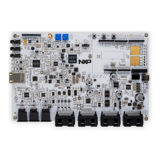
S32K344 NXP Semiconductors White Board Features overview The following figure shows the features of S32K344 White Board. Key features include the following: Figure 2. S32K344 White Board features overview • S32K344 BGA257 secured sample. • Safety SBC FS26 supplies MCU with 5V, 3.3V, 1.5V and monitors MCU status. -
Page 4: Connectors And Interfaces
• ARDUINO shield connectors can be used for compatible EVB installation (such as GD3000 EVB); • Specific connectors for 4G module communication via UART interface; Figure 3. S32K344 White Board connectors and interfaces The signals definitions of J32 are listed in the following table: Table 2. Signals definitions of J32... - Page 5 S32K344 NXP Semiconductors White Board Table 2. Signals definitions of J32 ...continued J32-1 D_IN_3 PEPS wake up J32-11 HB_OUT2 HB2001 out The signals definitions of J33 are listed in the following table: Table 3. Signals definitions of J33 Label Function Label Function...
- Page 6 S32K344 NXP Semiconductors White Board Table 5. Signals definitions of J31 Label Function Label Function J31-10 LIN8 LIN interface J31-20 J31-9 LIN7 LIN interface J31-19 J31-8 LIN6 LIN interface J31-18 CANL_3 TJA1145 CANL J31-7 LIN5 LIN interface J31-17 CANH_3 TJA1145 CANH...
-
Page 7: Mcu Pins Assignments And Board Resources Mapping
S32K344 NXP Semiconductors White Board MCU pins assignments and board resources mapping The hardware configurations and MCU PINs assignments are listed in below table. Table 6. White Board resources mapping Interface Reference/ Configuration Description Signals Power Input VBAT1/2/3 12V power supply input for this board... - Page 8 S32K344 NXP Semiconductors White Board Table 6. White Board resources mapping ...continued LPI2C0 (3.3V) Enabled MMA8452 (Accel Sensor, address 0x1D) SGTL5000 (Audio Codec, address 0x0A) CS2100 (Clock Multiplier, address 0x4F) FRAM (Fast EEPROM, address 0x57) CAN_0 TJA1044_1 PTA7_CAN0_TX, PTA6_CAN0_RX CAN_1 TJA1044_2...
- Page 9 S32K344 NXP Semiconductors White Board Table 6. White Board resources mapping ...continued LED D45 PTG1 (low active) LED D46 PTG2 (low active) Touch Sense Pad PTC23, PTE10 PTC24, PTE15 Slider PTD23, PTA11, PTD24, PTA14 General Analog Inputs A_IN_1 (0~12V) PTE21_ADC2_P3 Purpose Inputs...
-
Page 10: White Board Startup
The following figure shows the LED indicators for various power supplies on the board. Figure 4. S32K344 White Board features The 12V can be applied either through the power jack J3, connector J88 or the connector pins J33-9,10(GND)/J33-19,20(VBAT). The LEDs indicate the presence of power supply as following: •... -
Page 11: Power Supply
S32K344 NXP Semiconductors White Board Power supply The White Board requires an external power supply of 12V/1A, which is fed to the following devices on the board. • SBC FS26 – it powers the MCU with 5V (MCU VDD_HV_A domain), 3.3V (MCU VDD_HV_B domain) and 1.5V (MCU core). - Page 12 S32K344 NXP Semiconductors White Board Figure 6. Power supply topology The MCU has two power domains - VDD_HV_A and VDD_HV_B. On the white board, VDD_HV_A is supplied with 5V and VDD_HV_B is supplied with 3.3V and this configuration is fixed on the board. All 5V signals on the MCU are powered by VDD_HV_A and all 3.3V signals on MCU are powered by VDD_HV_B, so that the use of...
-
Page 13: Jumper Settings
S32K344 NXP Semiconductors White Board Jumper settings The following jumpers on the board are used for measuring the current consumption of the corresponding power supply: Table 7. Jumpers for current measurement Reference Position Description 1-2 Default Closed 12V power input after reverse protection diode... - Page 14 S32K344 NXP Semiconductors White Board Figure 7. Jumpers settings topology UM11919 All information provided in this document is subject to legal disclaimers. © 2023 NXP B.V. All rights reserved. User manual Rev. 1.0 — 11 April 2023 COMPANY PUBLIC 14 / 32...
-
Page 15: General Functional Description
8.1 MCU HW configuration 8.1.1 MCU power supply configuration S32K344 has two power domains – VDD_HV_A and VDD_HV_B. They can be supplied with either 5V or 3.3V. See below figure for PINs distribution for the two domains. The white board optimizes the PINs assignment to minimize the usage of voltage level shifters. -
Page 16: Mcu Reset Control
S32K344 NXP Semiconductors White Board Figure 9. External crystals for MCU 8.1.3 MCU reset control The MCU RESET pin is bidirectional. When acting as input, MCU can be reset either by push button “SW1” on the board or SBC RESET signal. When acting as output, some MCU internal failures (such as watchdog timeout) will pull RESET pin low and SBC can sense the MCU reset event and react accordingly. -
Page 17: Sbc Features
S32K344 NXP Semiconductors White Board Figure 10. Debug interface 8.2 SBC features 8.2.1 SBC and MCU connections The SBC and MCU on the White Board are shown in below figure. Figure 11. SBC and MCU on the White Board Connections between SBC and MCU are listed in below table. -
Page 18: Sbc Wakeup Function
S32K344 NXP Semiconductors White Board Table 10. SBC and MCU connections ...continued VDDIO VDD_HV_A PTA5_MCU_RESETB Interrupt input (PTG3) FCCU1/FCCU2 FCCU_ERR0 / FCCU_ERR1 (PTF16/PTF14) MUX-OUT ADC2_P7 input (PTE25) 8.2.2 SBC wakeup function • Wakeup input by external key-on signal (0V to 12V transition on WAKE1). -
Page 19: Communication Interfaces
S32K344 NXP Semiconductors White Board 8.3 Communication interfaces 8.3.1 Ethernet interfaces The ethernet switch SJA1105 is used and 4 ethernet interfaces are available on the board. One of them is 100BASE-TX which can be connected to PC for diagnostics and test. The other three interfaces are automotive ethernet (100BASE-T1). To meet SJA1105 current consumption requirements, a 3.3V buck circuit from FS56 and a 1.2V... -
Page 20: Usb To Uart Interface
S32K344 NXP Semiconductors White Board messages can wake up TJA1145. MCU configures TJA1145 operation modes by sending proper SPI commands. The device SJA1124 is a LIN controller and transceiver. MCU can use one SPI to access this device and generate 4 channels LIN interfaces. The other 4 LINs are linked to 4 LPUART modules on MCU. -
Page 21: Analog And Digital Inputs
S32K344 NXP Semiconductors White Board 8.4.1 Analog and digital inputs There are 2 general purpose digital inputs and 2 analog inputs on the White Board. Detailed PINs information can be found in Table 6. The analog input voltage can range from 0V~20V. -
Page 22: H-Bridge Driver
S32K344 NXP Semiconductors White Board 8.5 H-bridge driver There is an H-Bridge driver on this board which is controlled by MCU SPI interface. It can be used for brushed DC motor control. Figure 21. H-bridge driver - HB2001 8.6 Switch inputs detection The MSDI device CD1030 includes 21 switch-to-ground inputs and 12 programmable inputs (switch to battery or ground). -
Page 23: User Buttons
S32K344 NXP Semiconductors White Board Figure 23. User peripherals on the White Board 8.7.1 User buttons MCU PTC20 and PTC21 are used to monitor the user push buttons state. See the following figure for schematics of related circuits. Figure 24. User push button schematic 8.7.2 User LEDs... -
Page 24: Adc Rotary Potentiometers
S32K344 NXP Semiconductors White Board Figure 25. User LEDs schematic 8.7.3 ADC rotary potentiometers The two ADC POTs are linked to MCU PINs PTB13 and PTB14. See following figure for the schematic. Figure 26. User ADC inputs schematic 8.7.4 Touch sense pads There are two touch sense buttons and one touch sense slider on the White Board. -
Page 25: Io Headers For Extension Board
S32K344 NXP Semiconductors White Board Figure 27. User ADC inputs schematic 8.8 IO headers for extension board There are some IO Headers that can be used for external modules or EVB. See the following figure for these interfaces on the White Board. -
Page 26: Audio
S32K344 NXP Semiconductors White Board Figure 29. RF and LF circuit block diagram The RF circuit and LF circuit on the White Board are shown in the following figure. Figure 30. RF and LF circuit on the White Board 8.10 Audio The audio codec SGTL5000 can be used together with ethernet circuits to evaluate AVB application. -
Page 27: Others
The QSPI Flash (S25FL128L, 128Mbit) on the White Board can be used to store the firmware for S32K344 and other controllers connected to the vehicle network. The FRAM (MB85RC256VPF, 256Mbit) is used to store some NVM data in case quick write is needed during power down. -
Page 28: Abbreviations Used In The Document
S32K344 NXP Semiconductors White Board Abbreviations used in the document Table 11. Abbreviations White Board Body Control Module Domain Control Unit Gateway Audio Video Bridging Physical Layer Transceiver System Basis Chip Low Frequency MSDI Multiple Switch Detection Input High Side Driver... -
Page 29: Legal Information
NXP Semiconductors. In the event that customer uses the product for design-in and use in In no event shall NXP Semiconductors be liable for any indirect, incidental, automotive applications to automotive specifications and standards, punitive, special or consequential damages (including - without limitation - customer (a) shall use the product without NXP Semiconductors’... - Page 30 S32K344 NXP Semiconductors White Board Tables Tab. 1. Revision history ..........1 Tab. 7. Jumpers for current measurement ....13 Tab. 2. Signals definitions of J32 ........4 Tab. 8. Jumpers for VBAT power supply source ..13 Tab. 3. Signals definitions of J33 ........5 Tab.
- Page 31 S32K344 NXP Semiconductors White Board Figures Fig. 1. S32K344 White Board block diagram ....2 Fig. 17. CAN/LIN circuit block diagramUSB to Fig. 2. S32K344 White Board features overview ..3 UART circuit on the White Board ....20 Fig. 3.
-
Page 32: Table Of Contents
S32K344 NXP Semiconductors White Board Contents Introduction ............2 Features overview ..........3 Connectors and interfaces .........4 MCU pins assignments and board resources mapping ..........7 White Board startup ..........10 Power supply .............11 Jumper settings ..........13 General functional description ......15 MCU HW configuration ........15... - Page 33 Mouser Electronics Authorized Distributor Click to View Pricing, Inventory, Delivery & Lifecycle Information: S32K344-WB...
Need help?
Do you have a question about the S32K344 and is the answer not in the manual?
Questions and answers