Table of Contents
Advertisement
Quick Links
This user's guide describes the operational use of the TPS7A26EVM-021 evaluation module (EVM) as a
reference design for engineering demonstration and evaluation of the TPS7A2601DRV, low-dropout linear
regulator (LDO). Included in this user's guide are setup and operating instructions, thermal and layout
guidelines, a printed circuit board (PCB) layout, a schematic diagram, and a bill of materials (BOM).
Throughout this document, the terms demonstration kit, evaluation board, and evaluation module are
synonymous with the TPS7A26EVM-021.
Table 1
lists the related documentation available through the Texas Instruments web site at www.ti.com.
SBVU050 – December 2018
Submit Documentation Feedback
TPS7A26EVM-021 Evaluation Module
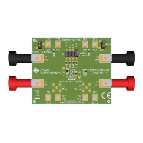
Figure 1. TPS7A26EVM-021 Evaluation Module
Table 1. Related Documentation
Device
TPS7A26
Copyright © 2018, Texas Instruments Incorporated
SBVU050 – December 2018
Literature Number
SBVS290
TPS7A26EVM-021 Evaluation Module
User's Guide
1
Advertisement
Table of Contents

Related Manuals for Texas Instruments TPS7A26EVM-021


Summary of Contents for Texas Instruments TPS7A26EVM-021
-
Page 1: Tps7A26Evm-021 Evaluation Module
TPS7A26EVM-021 Evaluation Module Figure 1. TPS7A26EVM-021 Evaluation Module This user’s guide describes the operational use of the TPS7A26EVM-021 evaluation module (EVM) as a reference design for engineering demonstration and evaluation of the TPS7A2601DRV, low-dropout linear regulator (LDO). Included in this user’s guide are setup and operating instructions, thermal and layout guidelines, a printed circuit board (PCB) layout, a schematic diagram, and a bill of materials (BOM). -
Page 2: Table Of Contents
Bottom Layer Routing ..................... TPS7A26EVM-021 Schematic List of Tables ..................... Related Documentation ....................TPS7A26EVM-021 BOM Trademarks All trademarks are the property of their respective owners. TPS7A26EVM-021 Evaluation Module SBVU050 – December 2018 Submit Documentation Feedback Copyright © 2018, Texas Instruments Incorporated... -
Page 3: Introduction
Introduction Texas Instruments' TPS7A26EVM-021 EVM helps design engineers evaluate the operation and performance of the TPS7A26 family of linear regulators for possible use in their own circuit application. This particular EVM configuration contains a single low-noise, high-PSRR linear regulator for high-speed communication systems. -
Page 4: Evm Setup
EVM Setup www.ti.com EVM Setup This section describes how to properly connect and setup the TPS7A26EVM-021, including the jumpers and connectors on the EVM board. Input/Output Connectors and Jumper Descriptions 2.1.1 J1 – IN Input power supply voltage connector. Twist together the positive input lead and ground return lead from the input power supply, and keep them as short as possible to minimize input inductance. -
Page 5: Soldering Guidelines
2. Enable the output by jumping J6 (the EN pin) to VIN. 3. Vary the respective load and input voltage, as necessary, for test purposes. SBVU050 – December 2018 TPS7A26EVM-021 Evaluation Module Submit Documentation Feedback Copyright © 2018, Texas Instruments Incorporated... -
Page 6: Pcb Layout
Figure 2 Figure 4 illustrate the PCB layout for this EVM. Figure 2. Assembly Layer Figure 3. Top Layer Routing Figure 4. Bottom Layer Routing TPS7A26EVM-021 Evaluation Module SBVU050 – December 2018 Submit Documentation Feedback Copyright © 2018, Texas Instruments Incorporated... -
Page 7: Schematic
OUT_S 2.2uF 2.2uF 2.2uF 2.2uF FB/NC IN_S OUT_S 100k 10.0k PG_S 0.01uF 499k TPS7A2601DRVR OUTPUT VOLTAGE 1.10M 301k 165k 57.6k Figure 5. TPS7A26EVM-021 Schematic SBVU050 – December 2018 TPS7A26EVM-021 Evaluation Module Submit Documentation Feedback Copyright © 2018, Texas Instruments Incorporated... -
Page 8: Bill Of Materials
These assemblies must comply with workmanship standards IPC-A-610 Class 2. Unless otherwise noted in the Alternate Part Number or Alternate Manufacturer columns, all parts may be substituted with equivalents. TPS7A26EVM-021 Evaluation Module SBVU050 – December 2018 Submit Documentation Feedback Copyright © 2018, Texas Instruments Incorporated... - Page 9 TI products. TI’s provision of these resources does not expand or otherwise alter TI’s applicable warranties or warranty disclaimers for TI products. Mailing Address: Texas Instruments, Post Office Box 655303, Dallas, Texas 75265 Copyright © 2018, Texas Instruments Incorporated...
Need help?
Do you have a question about the TPS7A26EVM-021 and is the answer not in the manual?
Questions and answers