Table of Contents
Advertisement
Quick Links
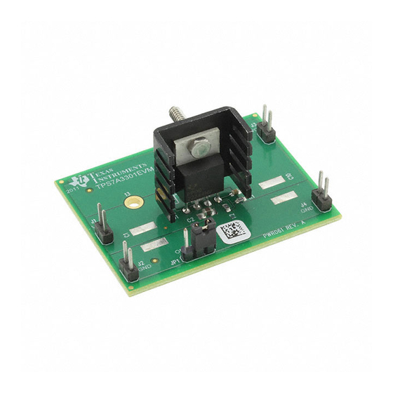
This User's Guide describes operational use of the TPS7A3301EVM-061 Evaluation Module (EVM) as a
reference design for engineering demonstration and evaluation of the TPS7A3301, low-dropout
negative-voltage linear regulator (LDO). Included in this user's guide are setup instructions, a schematic
diagram, layout and thermal guidelines, a bill of materials, and test results.
..................................................................................................................
1
Introduction
.........................................................................................................................
2
Setup
2.1
Input/Output Connectors and Jumper Descriptions
2.2
Equipment Setup
.....................................................................................................................
3
Operation
4
Adjustable
Contents
...................................................................................................
SLVU602 – November 2011
TPS7A3301EVM-061
...........................................................
User's Guide
1
2
2
2
2
Advertisement
Table of Contents

Subscribe to Our Youtube Channel
Related Manuals for Texas Instruments TPS7A3301EVM-061


Summary of Contents for Texas Instruments TPS7A3301EVM-061
- Page 1 SLVU602 – November 2011 TPS7A3301EVM-061 This User’s Guide describes operational use of the TPS7A3301EVM-061 Evaluation Module (EVM) as a reference design for engineering demonstration and evaluation of the TPS7A3301, low-dropout negative-voltage linear regulator (LDO). Included in this user’s guide are setup instructions, a schematic diagram, layout and thermal guidelines, a bill of materials, and test results.
-
Page 2: Equipment Setup
1. R1 and R2 can be calculated for any output voltage using Equation 1 and the Vref voltage found in the device data sheet under the Electrical Characteristics. SLVU602 – November 2011 TPS7A3301EVM-061 Submit Documentation Feedback Copyright © 2011, Texas Instruments Incorporated... -
Page 3: Test Results
For additional information on adjustable operation, see the TPS7A3301 data sheet (SBVS169). Test Results This section provides typical performance waveforms for the TPS7A3301EVM-061 printed circuit board. Turnon Sequence shows the hard turnon characteristic where –VIN is –18 V, EN (C1, yellow) is switched on to –18 Figure 2 V and the output drives a 1-A load (C4, green). - Page 4 Realistically, the user can only control two resistances, θ and θ . Therefore, for a device with a known θ , θ and θ become the main design variables in selecting a heat sink. SLVU602 – November 2011 TPS7A3301EVM-061 Submit Documentation Feedback Copyright © 2011, Texas Instruments Incorporated...
-
Page 5: Board Layout
û This information allows the user to select the most appropriate heatsink for any particular application. The heat sink chosen for the TPS7A3301EVM-061 (507302B00000G from Aavid) has a specified thermal resistance (θ ) of 24°C/W. There is also an option of using the two large mounting holes (13 and 14 –... - Page 6 Board Layout www.ti.com K002 Figure 5. Top Layer Routing SLVU602 – November 2011 TPS7A3301EVM-061 Submit Documentation Feedback Copyright © 2011, Texas Instruments Incorporated...
- Page 7 K003 www.ti.com Schematic and Bill of Materials Figure 6. Bottom Layer Routing Schematic and Bill of Materials Figure 7. TPS7A3301EVM-061 Schematic SLVU602 – November 2011 TPS7A3301EVM-061 Submit Documentation Feedback Copyright © 2011, Texas...
- Page 8 Schematic and Bill of Materials www.ti.com Table 1. TPS7A3301EVM-061 Bill of Materials RefDes COUNT Value Description Size Part Number Capacitor, ceramic, 50 V, 47 µF 2220 X5R, 10% Capacitor, ceramic, 50 V, 1 µF 0805 X5R, 10% Capacitor, ceramic, 50 V, 1 µF...
-
Page 9: Evaluation Board/Kit Important Notice
Evaluation Board/Kit Important Notice Texas Instruments (TI) provides the enclosed product(s) under the following conditions: This evaluation board/kit is intended for use for ENGINEERING DEVELOPMENT, DEMONSTRATION, OR EVALUATION PURPOSES ONLY and is not considered by TI to be a finished end-product fit for general consumer use. Persons handling the product(s) must have electronics training and observe good engineering practice standards. -
Page 10: Regulatory Compliance Information
EVALUATION BOARD/KIT/MODULE No license is granted under any patent right or other intellectual property right of TI covering or relating to any machine, process, or combination in which such TI products or services might be or are used. TI currently deals with a variety of customers for products, and therefore our arrangement with the user is not exclusive. - Page 11 FCC Interference Statement for Class B EVM devices This equipment has been tested and found to comply with the limits for a Class B digital device, pursuant to part 15 of the FCC Rules. These limits are designed to provide reasonable protection against harmful interference in a residential installation. This equipment generates, uses and can radiate radio frequency energy and, if not installed and used in accordance with the instructions, may cause harmful interference to radio communications.
- Page 12 Also, please do not transfer this product, unless you give the same notice above to the transferee. Please note that if you could not follow the instructions above, you will be subject to penalties of Radio Law of Japan. Texas Instruments Japan Limited (address) 24-1, Nishi-Shinjuku 6 chome, Shinjuku-ku, Tokyo, Japan http://www.tij.co.jp...
- Page 13 EVALUATION BOARD/KIT/MODULE (EVM) WARNINGS, RESTRICTIONS AND DISCLAIMERS For Feasibility Evaluation Only, in Laboratory/Development Environments. Unless otherwise indicated, this EVM is not a finished electrical equipment and not intended for consumer use. It is intended solely for use for preliminary feasibility evaluation in laboratory/development environments by technically qualified electronics experts who are familiar with the dangers and application risks associated with handling electrical mechanical components, systems and subsystems.
-
Page 14: Important Notice
IMPORTANT NOTICE Texas Instruments Incorporated and its subsidiaries (TI) reserve the right to make corrections, enhancements, improvements and other changes to its semiconductor products and services per JESD46, latest issue, and to discontinue any product or service per JESD48, latest issue.
Need help?
Do you have a question about the TPS7A3301EVM-061 and is the answer not in the manual?
Questions and answers